This thread has been locked.
If you have a related question, please click the "Ask a related question" button in the top right corner. The newly created question will be automatically linked to this question.
Since this is about a different board I reply in this thread:
The question was:
Not sure if I should start a new thread, for now I'll add this data here.
We have tested three setups: 1) Launchpad, 2) Custom CC1310+CC1190, 3) Launchpad + RF Gain TRF37C73
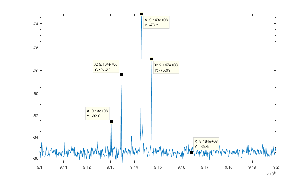
With the CC1310 set to 0 dBm and the PA with HGM=0, we have peak supply currents (3.3 V) of 7.6 mA, 59.4 mA, and 61.9 mA, respectively. Doing an indoor walk test has options 2) slightly worse than 1), and 3) is more than triple the distance of either. We borrowed a spectrum analyzer to get the following measurements (there is a 20 dB attenuator on the input).
----
Looking at the pictures: How have you measured this? Did you use CW or packets on the transmitter side? It looks like you could be sending packets/ modulated signal and just capturing part of the transmitted power. Try to send a CW.
The latest plot using the TRF looks like you are sending a CW.
Measurement was done by taking our development boards and swapping the location of a zero-ohm resistor to send the RF signal to an SMA port instead of the antenna. The SMA port was connected to a SSA3000X from Siglent through a DC block and 20 dB attenuator. All transmission plots (including the TRF) consists of packets, and the Siglent was setup to trigger on signals greater than -80 dBm. I will report back when I have a chance to rerun this test with CW transmission.