This thread has been locked.

If you have a related question, please click the "Ask a related question" button in the top right corner. The newly created question will be automatically linked to this question.

CC1310: Having trouble with programming custom cc1310 boards

Part Number: CC1310


I am having trouble getting a custom cc1310 board to connect via cJTAG for flash programing.

Chip is new never before programmed. We have 2 custom boards to do a collector/sensor with our extra I/Os.  Both board have the same trouble but are of similar design.
Pins assignment are the same as i had set up and working in LauchPad.

I am using the debugger on the lauchpad (XDS110) and have jumpered over to our
TCK,TMS,TDI,TDO,GRN, & VDD-ref to center of v source jumper on lauchpad.

We can measure 3V out of the dc/dc intrnal regulator. I assume this means chip is powered and grounded(can't see under chip).

We did have ESD/levelers on the JTAG lines as in the launchpad, but have removed and tried without(same results). The only other thing in the JTAG circuit is the traces.


CCS
Error connecting to the target:
(Error -242 @ 0x0)
A router subpath could not be accessed.
The board configuration file is probably incorrect.
(Emulation package 7.0.100.1)


RF-Flash prog2 giving (using primarly 2 pin cJTAG setting, but tried 4 pin too)
- unknown device (Debugger is recognized but not chip)

forced mas erase fails with :
>Initiate access to target: XDS-L2000GPR.
>Create XBAL object failed: Target connect failed
>Failed to create device object.


Are ther anymore checks that can be made to confirm CPU is running?
Once I do get it to connect do I used the .hex or .out file from the project to send?

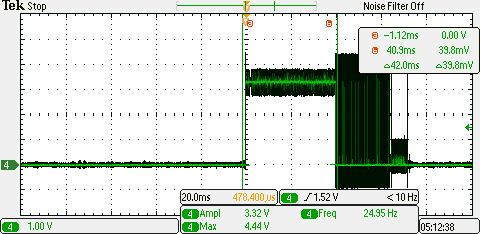
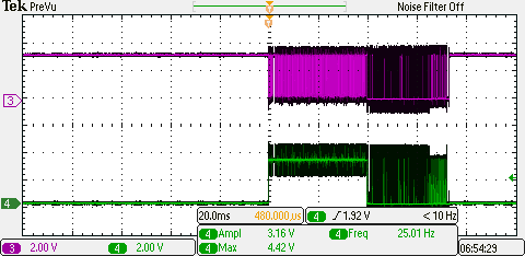
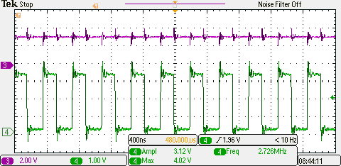
Below are some captures of the TCK & TMS during connect attempts. Our board does seem to have more overshoot / oscilation stabilizing new level, but not sure if it is enough to make a difference.

TMS ( at different time sample rates)

TCK(left), TCK(pruple) & TMS(green) (right image)

Any suggestions on where to go next? Please..

  • With ESD/level removed.

  • - "We can measure 3V out of the dc/dc intrnal regulator": On which pin do you measure 3 V? DCOUPL should be 1.2 V, VDDR = 1.65 V.

    - The signals needed to debug the CC1310 are TCK, TMS and SRST_N (RESET_N).

    - The picture below shows how the XDS110 on the LP could be used to debug a target with a different voltage. Here, the upper LP is the XDS110.

  • Starting to think DC/DC or ground is the problem.

    Measuring decoupling capacitors as close to chip as possible:

    VDDS (pins 13,22,44)  3.2V from supply

    VDDS_DCDC(pin34) 3.2V from supply

    VDDR (pins 45,48) 3.0V

    DCOUPL (pin 23) 3.2V

    Also see a 3.2V on TCK & TMS when not connected and abut 1V on some GPIO pins that are not connected.

    Could the lack of base grounding cause this? Local shop mounted the CPU for us for our class project and we did not watch the mounting.

    Are there any other thing that would cause DC/DC have bad output?

  • If DCOUPL and VDDR is 3 V either the schematic/ layout is not according to the ref design and/ or you have assembly errors. The die paddle is the chip ground and it's very important that this is grounded as in the ref design.
  • On our other similar (slightly different I/Os) custom board (collector side).
    Values are also wrong but dfferent than our (sensor custom board).

    VDDS (pins 13,22,44) 3.2V from supply
    VDDS_DCDC(pin34) 3.2V from supply
    VDDR (pins 45,48) 1.0V
    DCOUPL (pin 23) 0.8V
  • I would guess a assembly error etc are causing VDDR/ DCOUPL to be a bit random on your boards
  • OK we found part of our trouble. Wrong value capacitor on DCOUPL.
    We replaced it on both our boards.

    One board this corrected VDDR to 1.8V but the DCOUPL is also getting 1.8V (not expected 1.27).
    Other board it did not correct. Still getting 3V on VDDR & 2.8 on DCOUPL.

    Thought is internal chip regulators may be destroyed? Any opinion?
  • If the boards have had high higher voltages than expected on the VDDR and DCOUPL pins some parts have probably been damaged. I would try to change the CC1310 on the boards.
  • Will change  CC1310 chips on Monday and see what difference we get.

  • Tried changing MCU and had the same so started over from scratch.  We had extra PCB and put on board just MCU on with power decoupling and 24M xtal. This gave correct voltage and recognized in programer2.  So trouble is with some other parts on the board.  Added RF components and still OK.  We are continuing to build up board slowly part at a time.

    Tried to do a test with our code(collector-sensor modified project) to see if we had RF and ran into a different problem.

    After executing some code it calls BIOS start then hangs waiting for an interrupt. If I pause is debugger it always is at cpu.h CPUwfi(). It never gets to Csf_init(). Is there a problem with my 32K clock? We have not added that crystal yet but 

    Added  in ccfg.c #define SET_CCFG_MODE_CONF_SCLK_LF_OPTION            0x3        // LF RCOSC

    expected that this would allow us to use the internal RTC oscillator, not sure if I did this wrong or am having a different problem?

    I also noted that CCS reloads code every time i start debug.  Is this normal if the code did not change?

    Thanks for any ideas.

  • Did determine that ground was the problem on boards that local rework shop did for us. We fixed one of theirs. Still working on building up the reset of our school project board, but working on figuring out getting the SW running on custom board at the same time.
    We are using the same IO pins as we did on the launchpad for connecting to our buttons, LEDs, and display.
    As such we just loaded the same code as the launchpad (did not try doing custom board file). Previously asked and was told should work, but also know the LauchPad has external flash chip. Our board doesn't have that. Does this require us to change anything in the collector-sensor project for our board?
  • Most examples do not use the external flash. One exception is the OAD examples. Meaning that using the examples you mentioned should not be an issue without external flash. Also for testing I would start with some of the very basic examples to test the fundamental functionality.
  • Proper chip grounding fixed power trouble.
    SW is running OK now that 32K xtal has been installed.