This thread has been locked.

If you have a related question, please click the "Ask a related question" button in the top right corner. The newly created question will be automatically linked to this question.

CC1120: CC1120 sleeps on entry into RX, TX, or FSTXON states

Part Number: CC1120

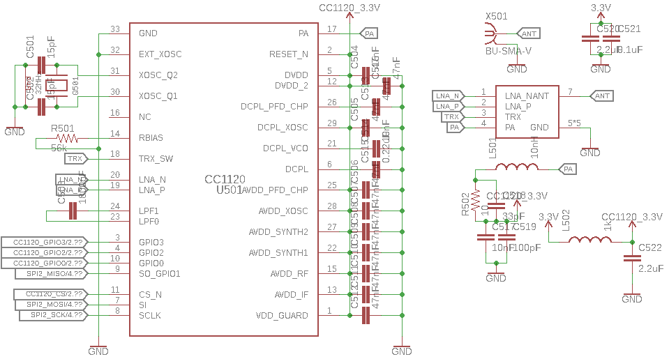
I currently have two CC1120s set up in the following configuration: 1 TI CC1120 evaluation module connected to the SOC-BB-Battery Board for System-on-Chips which is connected to an Arduino via an SPI interface and another on a custom designed PCB which uses a Teensy 3.5 as a MCU (Eagle CAD schematics for this can be provided upon request for debugging purposes). I have adapted the published SPI interface for the CC1120 to work with the Teensy/Arduino hardware (our software can also be provided upon request). This software is able to control the evaluation module connected to the Arduino without any errors as far as we have detected. However, using the same software on our custom Teensy-based board, the radio seems to go into the sleep state (MARC state of 0x00) whenever we issue the SRX, STX, or SFSTXON command strobes (note that it only does this for the STX command strobe if we tell the radio to remain in the TX state after strobing STX - otherwise it returns to IDLE after STX). I have verified that the radio is going through BIAS_SETTLE and REG_SETTLE MARC states before going to sleep.

Considering that the same code produces different results on the EM and our custom board, I am wondering if there are any hardware connections I might have accidentally made that would cause this behavior.

  • Have you verified that it's actually in sleep by measuring the current consumption? Or are you just reading a marc state that indicate this? If the later I would assume that you have not implemented the SPI interface correctly. 

    Please post a plot of the 4 SPI lines when you do the above for verification. 

  • I checked the voltage on most of the power pins (VDD_GUARD, DVDD, etc.) and it drops from 2.5V to 1.5V when I try to switch to RX or TX. I'm pretty sure this does indicate that the current is dropping and that the ship is going to sleep, but correct me if I'm wrong.

    Are you referring to the software SPI interface? Because I am fairly sure that the software interface is implemented correctly because the same code is working to communicate with the CC1120 EMK from a regular Arduino. If you are referring to the hardware SPI interface, I am pretty sure this is correct as well as I can communicate normally with the CC1120 on our board for most functions besides going to RX and TX states. Since the chip is on our board, I'm not sure how I can probe the SPI lines, but I will check with some people on site that might know more and try to produce those plots. In the mean time I have attached our schematic for our board (in Eagle CAD) which has the schematic for the CC1120 in it in case this can help provide any more insight.

    rev5.zip

  • The voltage on the power pins should not drop if you change state. The exception is the dcoupl pin which goes to 0 due to the digital regulator turning off . 1.5 V is below the voltage the chip is designed for and hence the state is not defined. I haven't checked the design files since i'm not at a pc but it could sound like a hardware issue. Schematics should be provided as pdf since it's not given that we have the same tools you use.
  • It occurred to us that, since we are debugging this board on USB power, that the radio might be drawing too much current from the USB port when it tries to send or receive packets. Could this cause such a voltage drop in the chip? I'll have a chance to test this with a debugging power supply later today and will respond if more available current resolves the issue. Thanks for your help so far and sorry about the format of the CAD. I will upload a PDF version in my next post if the issue isn't resolved.
  • Using the desktop power supply, I was not able to resolve the issue. However, I did confirm that the current consumption of the entire board goes from 90mA to 120mA when the rx strobe command is issued (although the marc state is still 0x00) and remains there. The voltage on the power pins also falls to about 1.5V in this state. I've attached an exported png of our CC1120 schematic. Let me know if you require any other potions of the schematic and thanks in advance for any insight.

  • All DCPL pins should only be connected to a decoupling cap. In this schematic DCPL_XOSC is connected to 3.3 V. 

  • Hello. Just wanted to update and close out the thread. The issue turned out to be that we accidentally used a high frequency inductor in the power filter circuit. The resistance of this component was too high and caused a brownout when the current increased for the send or receive modes (thus the aforementioned voltage drop). Thanks for your help on this issue.