This thread has been locked.

If you have a related question, please click the "Ask a related question" button in the top right corner. The newly created question will be automatically linked to this question.

CC1310: working under -20 degree

Part Number: CC1310
Other Parts Discussed in Thread: ENERGYTRACE, , CC1350, MSP430FR5969, MSP-EXP430FR5969, SIMPLELINK-CC13X0-SDK

Hello!

My 1310 4x4 device based on this ref. design: SimpleLink CC1310 IPC 4-Layer 4x4 Differential 779-930 MHz v1.0.1 Design Files

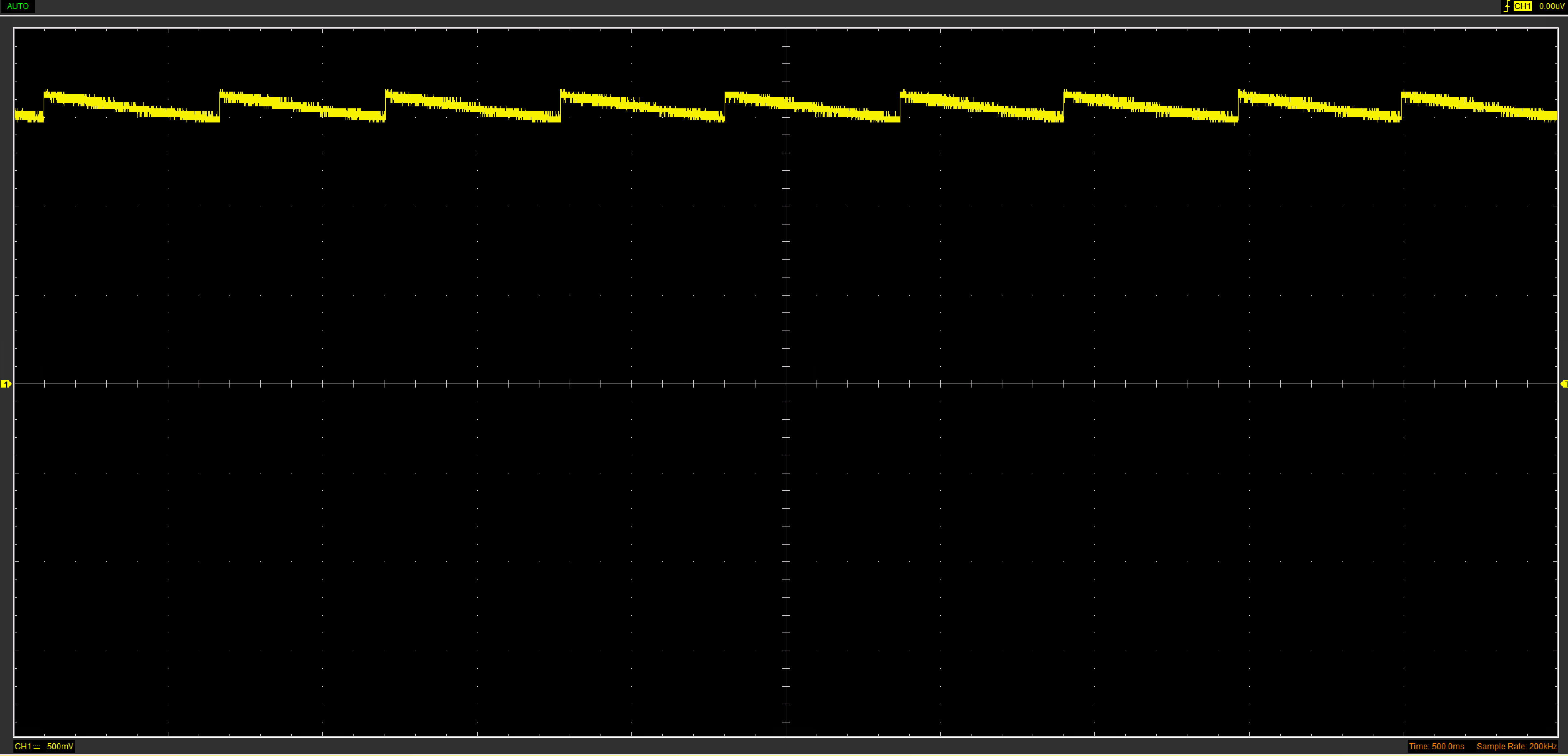
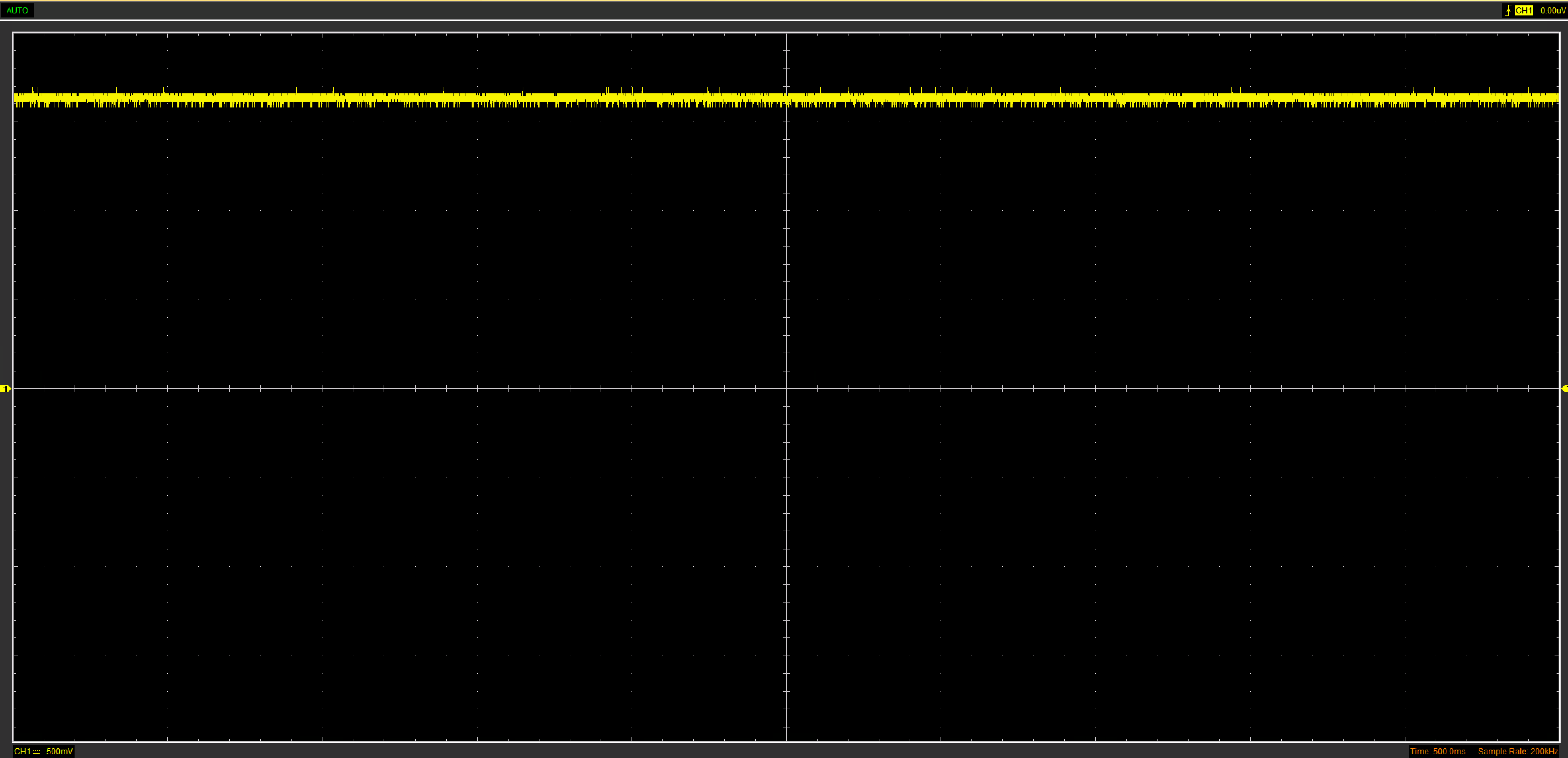
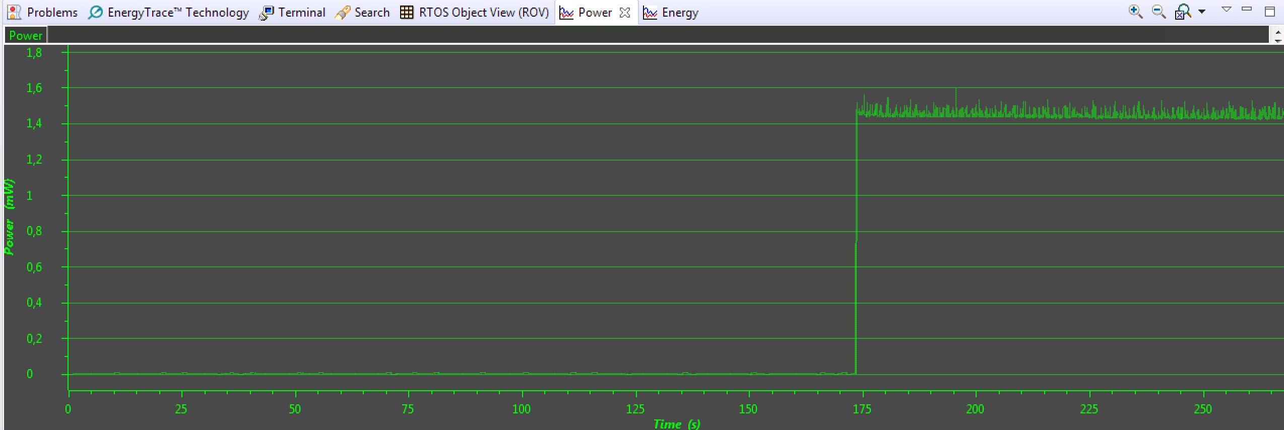
I encountered a problem: then device working under -20 Celsius degrees, after about 1 hour, current consumption in sleep mode rises from 0.7 uA to 470 uA. Measured by EasyLinkTX example + EnergyTrace. After power cycle (without removing device from freezer) current drops back to 0.7 uA. If after 1 hour i call SysCtrlSystemReset() - device hangs and current rises to 4000 uA. If i remove device from freezer (without power cycle) - current still 470 uA.  

If i call SysCtrlSystemReset() every 10 seconds (in freezer) - all ok.

In room temperature - all ok.

Schematic, Layout and BOM: 5314.CC1310_TempV1.zip


  • Hello Rustem,

    do you mean -20 Celsius degrees?
    Steam condensation may cause a huge leakage.
    In my modest opinion, all LaunchPads are designed to work in a non steam condensing environment.

  • Hello!
    Yes, i mean -20 Celsius degrees.
    Thank you for a quick answer, but this not explain returning to 0.7 uA after power cycle (without removing device from freezer).
    My LaunchPads (cc1310, cc1350) works fine in freezer, i have a problem only with my device.
  • Hello Rustem,

    Do you have any other components in the design than the components used in the reference design? Have you used components with the same temperature rating etc.? If possible, can you share your schematics here on E2E?

    Best regards,
    Simon

  • Hello!

    I used the same components.

    Here the Schematic, Layout and BOM:

    CC1310_TempV1.zip

  • Thanks!

    Which EnergyTrace HW and debugger are you using? Is it placed in the freezer together with your board?

    -Simon
  • I used MSP430FR5969 LaunchPad (with EnergyTrace feature) as power source with GND and VCC wires only. I do not use any debuggers. LaunchPad is not in freezer. In freezer is only my device.
  • Can you redo the test without U2, R8 and R7 mounted on the board?

    Thanks,
    Simon
  • Done. Same results, current 0.4 mA in sleep mode after 30 minutes.

    I also found that if i call SysCtrlSystemReset() every 10 seconds (in freezer) - all ok.

  • Thanks Rustem! We then need to find out what else can be different between your design and the LaunchPad.

    1. Is the exact same FW running in both setups?
    2. Can you share your code?
    3. Are you using MSP-EXP430FR5969 to only measure the current and not using debug functionality/JTAG interface?
    4. Is the debugger connected while the target is in the freezer?
    5. How did you connect the debugger?
    6. Is the battery disconnected and target being powered from the debugger in both setups?

    Thanks,
    Simon
  • 1. Yes, for all tests i use rfEasyLinkTx example from SIMPLELINK-CC13X0-SDK v1.6 with only 1 additional string of code "Task_sleep (1000000);" in main loop, and i disabled led blinking.

    2. Here:rfEasyLinkTx_CC1310_LAUNCHXL_tirtos_ccs.zip

    3. Yes. I also measured current with Fluke 87V, results are same

    4. No

    5. Not connected

    6. Yes

    Different's between my design and LaunchPad:

    2 layers - 4 layers

    IPC (Integrated passive components) - some passive components

    cc1310 4x4  - cc1310 7x7

  • Not sure what is going on, debugging in remote hardware is always a bit tricky.

    - Do you see the same if you disable the DCDC in ccfg.c?
    - Do you see any difference when monitoring VDDR when you enter the 470 uA state?
  • 1. After changing ccfg.c i see the same.
    I made this changes:
    CCFG_FORCE_VDDR_HH 0x0
    SET_CCFG_MODE_CONF_DCDC_RECHARGE 0x1
    SET_CCFG_MODE_CONF_DCDC_ACTIVE 0x1
    2. After enter in 470 uA state VDDR becomes constant: 1.95V before changing ccfg.c, 1.67V after changing.
    In 0.7 uA state VDDR is floating: 1.88V-1.94V before changing ccfg.c, 1.58V-1.66V after changing
  • Are you able to use a scope and make a screenshot of the waveform in both cases?
  • 0.7 uA state

    470 uA state

    Time to transition from 0.7uA to 470 uA - less then 15 minutes.

    I also found that my previous version of the same board works fine in freezer (for two hours). But it's have a 4 layers. Problem board have 2 layers.

    I have other similar small boards (leak detector, photo detector) with 2 layers. All of them have this problem in freezer, but works fine in room temperature.

  • Based on this and the current consumption it looks like you end up in the IDLE state.

    Could you try to run on the internal 32 kHz RCOSC to see if this is caused by some strange 32 kHz xosc issue? (Not sure at the moment how you can end up in IDLE but if for some reason the sleep count get lost it could be that you end up in an error state of sorts)
  • You mean this option in ccfg.c ?:
    #define SET_CCFG_MODE_CONF_SCLK_LF_OPTION 0x3 // LF RCOSC
    I tried. Results are same (including waveform)

    I also tried to put device in sleep mode to 1 hour right after start (before first transmission). Device comes to 470 uA mode after < 20 minutes, before first wake up.

  • - Since it doesn't look like it's related to the 32 kHz xtal it would be useful to check the 24 MHz xtal if that start up.
    - If you use the pin standby example, do you see the same then? If this gives the same 470 uA state: I haven't looked into the details but I believe that for this example it should be possible to only use the HF RCOSC (not turn on the 24 MHz xtal) and see if the issue is related to the 24 MHz xtal.
    - Does the current goes directly from 0.7 uA to 470 uA with no overshoot etc?
  • 1. pinStandby example comes to 470 uA state in 3 minutes. I found that temperature difference is related with time that needed to transit from 0.7 uA state to 470 uA state. If chip already frozen (-20 degree) it comes to 470 uA state in 1 hour. I also found that rebooting every 10 seconds is not a solution - my other test chip, that rebooted every 10 seconds, hangs after 50 hours in freezer (if i reboot (by SysCtrlSystemReset()) the chip while it in 470 uA state - it hangs and consume > 2 mA).

    2. How can i turn off 24 MHz xtal? I can not find this option in ccfg.c.

    3. Yes,  current goes directly from 0.7 uA to 470 uA. Here the graph from EnergyTrace (it's pinStandby example with 1 wake up every 5 seconds):

  • Hi Rustem,

    the radio CPU does the process called frequency synthesizer calibration.

    RFHWIFG register contains FSCA field.

    Maybe I am wrong, but looks to me that the radio CPU does some things in a background when a temperature changes by some threshold value.

    I remember that in case of CC32xx, the RF calibration is invoked when temp. changes by 20 degC since the last calibration.

    In case of CC32xx, the calibration takes effect when exiting the hibernate state or during normal operations.

    I know that your design based on a 4 layer PCB works fine.

    However, I have no better idea right now.

    Could you check FSCA interrupt flag before and after current  jumps to 470 uA?

  • Tomasz: The current consumption indicate that the RF core never start and the issue is still present when using the pin examples which do not use RF.

    Rustem: Your are right, it doesn't look like it's easy to switch to HF RCSOC. Are you able to sniff on the xtal pins to see if the xtal starts etc? Note that you can't probe directly on the pins, you have to measure without physical contact.
  • I have spectrum analyzer and i can measure crystal oscillator's error rate. But i do not know how to "sniff xtal pins". If you can point me to proper test setup - i will make measurements.

  • TER: I do remember that 1310 uses about 50 uA/MHz. I imagine that RF core starts an ISR just for a few us and do not turn off the RF synthesizer, maybe something else.
    Should these few us be seen on Energy Trace presented by Rustem? I have no experience.
    Pin examples do not use RF, however RF interrupts system has some defaults.

    Somewhere earlier Rustem has said there were no problems with his LPs: CC1310, CC1350.
    In case that RFHWEN register has different settings on LPs and on this terrible board, RF interrupt subsystem may do something.

    I summarized all currents except: I2S, SSI, UART from the table above and I got 525 uA.
    From my perspective 525 is equal to 470.

    If this big issue is driven by delta Temp SysCtrlSystemReset() calls should serve as a workaround.

    I would change 10s interval to 100ms and would observe how long  it lasts.

  • Rustem: I believe that you should be able to see the xtal swing if you attach a antenna to the spectrum and place the antenna as close as possible to the xtal pins.
  • I tried on the working board with no results. That frequency i must set on spectrum?

    I can catch signal on 48 MHz only if main MCU spends a lot of time (> 200 ms) in Active mode.

    And i do not understand, how XTAL can not work in 470 uA state, because in this state board is fully functional (sends correct radio packets than i use EasyLinkTx example for tests), only consumes too much power in sleep mode.

  • It could be that I looked at this from the wrong end. Could you check if 5.4 in www.ti.com/.../swcu117h.pdf could be relevant in this case?
  • Yes, this is it!
    Thank you very much, i will never find it without you!
    It's strange that this traffic on TCK pin happen, because device under test was inside plastic case and nobody touched it.
    1. May be you can point me to the document which guarantee safe device work in production with "to do" list like that:
    "- short TCK pin to VCC after flashing the device to prevent unwanted transition to debug mode
    - ...."?
    2. Can i completely disable debug and other unsafe features of chip after production?
  • You have a couple of options:

    - Don't use JTAG at all and tie the TCK pin. Use the bootloader to flash the device

    - Disable the JTAG in the CCFG file. Also see chapter 9 in the TRM. You should consider to disable the jtag anyway since normally you don't want anybody to potentially alter the functionality of your device.