This thread has been locked.

If you have a related question, please click the "Ask a related question" button in the top right corner. The newly created question will be automatically linked to this question.

RTOS/CC1310: cc1310 SPI CNS Interrupt Problem

Part Number: CC1310

Tool/software: TI-RTOS

Hi 

I am currently working on an example of using SPI.

Using sdk:  simplelink_cc13x0_sdk_1_60_00_21

ccs version : 7.4.0.00015 

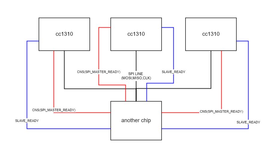
I want to implement SPI communication using SPI's CSN.

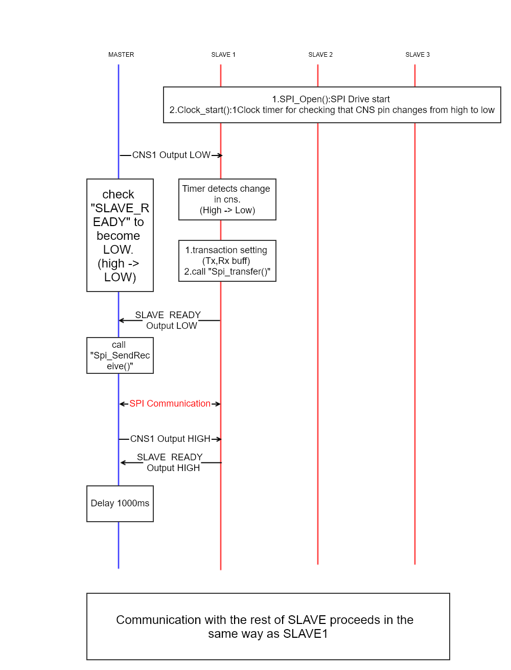
The behavior of my SPI example is as follows.

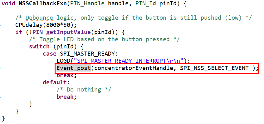
- Interrupt occurs when CNS goes low from HIGH.
- If interrupt occurs, call Event_post (SPI_NSS_SELECT_EVENT) to perform SPI communication.

<project code setting>

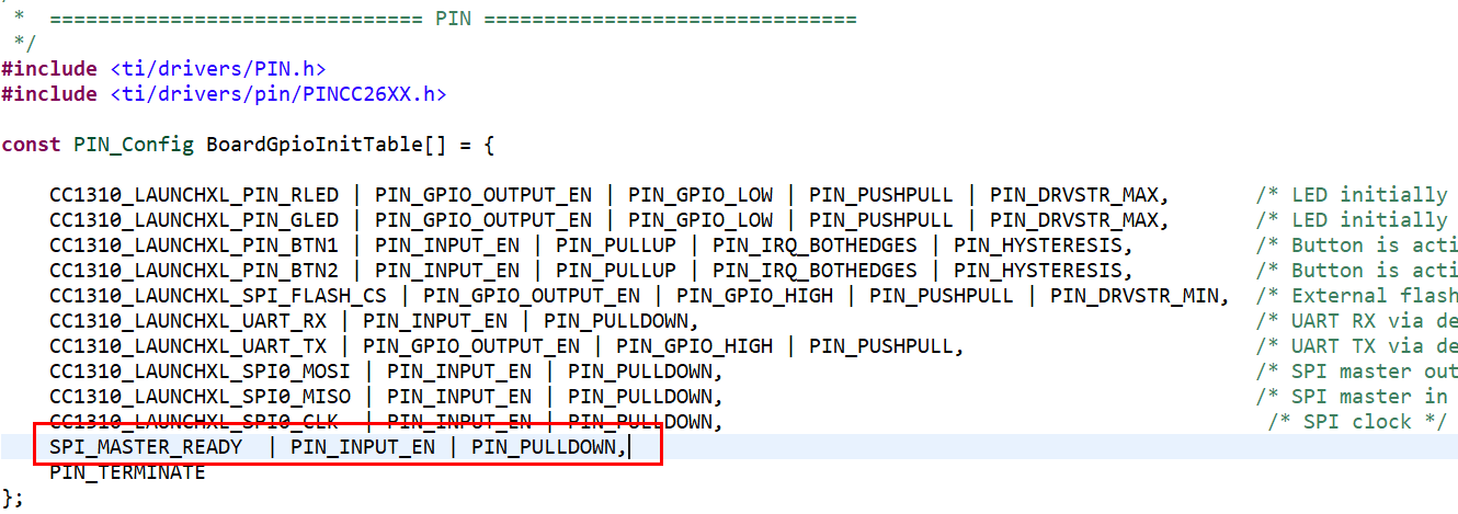
First, make the following settings in CC1310_LAUNCHXL.h.  (My CSN is IOID_15.)

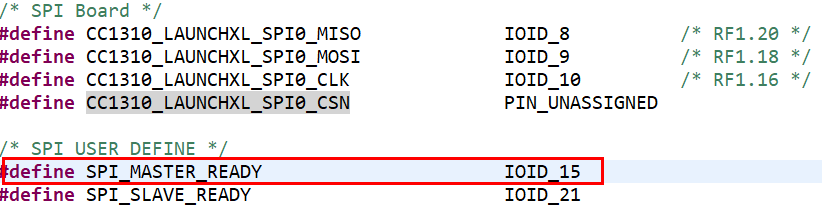
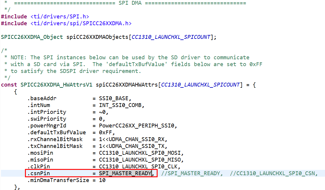
Then make the following settings in CC1310_LAUNCHXL.c.

(pin_init setting  ,  SPI HWAttribute setting)

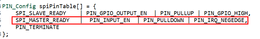
and To receive an interrupt, I set the interrupt on the csn pin. 

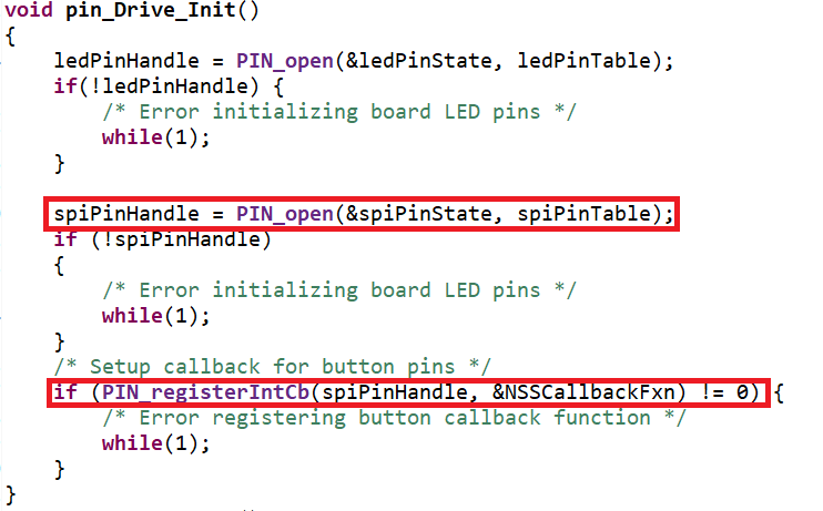
There is a problem here.

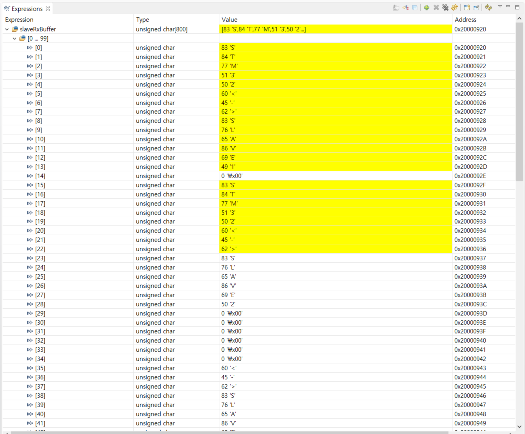
I did debugging because the program did not work properly.

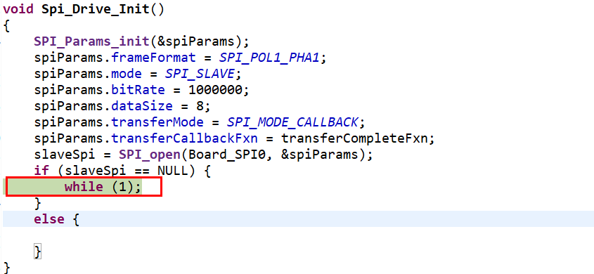
It seems that spi is not open.
Is there a way to use the pin specified by csn as an interrupt?

thanks

  • Since you are controlling the csn pin externally, then you should remove that pin from the SPI HWAttr list. The you will be able to do what you want.
  • What does "controlling the csn pin externally" mean?

    Do I have to use the CSN pin and communication Ready pin separately?
  • Since you want another chip(master) to set CSN low when it's ready, then the CSN is controlled externally.

    In your SW, you assigned CSN pin to your spiPinTable and then after you do PIN_open, the SPI_MASTER_READY pin belongs to spiPinHandle.

    When you try to do SPI_open, that function will also try to assign SPI_MASTER_READY to slaveSpi, then you have a conflict. This is what caused you to have a NULL slaveSpi handle.

    To avoid this, you need to remove SPI_MASTER_READY pin from the HWAttrs table. Just set it as NULL.
  • Refer to your advice and reconfigure master-Multi_Slave.
    The detailed communication situation is as follows.

    1.H / W configuration

    -Multi slave's mosi, miso and clk are used in common.

    -CNS and SLAVE_READY are used for each slave.

    2.Master-MultiSlave Communication sequence


    3.CC1310 slave Setting 

        (1). First, set the CNS pin as follows (pin_init setting  ,  SPI HWAttribute setting)

         - CC1310_LAUNCHXL.h  (CNS,SPI Setting)


    /* SPI Board */
    #define CC1310_LAUNCHXL_SPI0_MISO             IOID_8          /* RF1.20 */
    #define CC1310_LAUNCHXL_SPI0_MOSI             IOID_9          /* RF1.18 */
    #define CC1310_LAUNCHXL_SPI0_CLK              IOID_10         /* RF1.16 */
    #define CC1310_LAUNCHXL_SPI0_CSN              PIN_UNASSIGNED
    
    /* SPI USER DEFINE */
    #define SPI_MASTER_READY                      IOID_15
    #define SPI_SLAVE_READY                          IOID_21

         - CC1310_LAUNCHXL.c  (CNS setting)

    const SPICC26XXDMA_HWAttrsV1 spiCC26XXDMAHWAttrs[CC1310_LAUNCHXL_SPICOUNT] = {
        {
            .baseAddr           = SSI0_BASE,
            .intNum             = INT_SSI0_COMB,
            .intPriority        = ~0,
            .swiPriority        = 0,
            .powerMngrId        = PowerCC26XX_PERIPH_SSI0,
            .defaultTxBufValue  = 0xFF,
            .rxChannelBitMask   = 1<<UDMA_CHAN_SSI0_RX,
            .txChannelBitMask   = 1<<UDMA_CHAN_SSI0_TX,
            .mosiPin            = CC1310_LAUNCHXL_SPI0_MOSI,
            .misoPin            = CC1310_LAUNCHXL_SPI0_MISO,
            .clkPin             = CC1310_LAUNCHXL_SPI0_CLK,
            .csnPin             = SPI_MASTER_READY, 
            .minDmaTransferSize = 10
        },


    const PIN_Config BoardGpioInitTable[] = {
    
        CC1310_LAUNCHXL_PIN_RLED | PIN_GPIO_OUTPUT_EN | PIN_GPIO_LOW | PIN_PUSHPULL | PIN_DRVSTR_MAX,       /* LED initially off          */
        CC1310_LAUNCHXL_PIN_GLED | PIN_GPIO_OUTPUT_EN | PIN_GPIO_LOW | PIN_PUSHPULL | PIN_DRVSTR_MAX,       /* LED initially off          */
        CC1310_LAUNCHXL_PIN_BTN1 | PIN_INPUT_EN | PIN_PULLUP | PIN_IRQ_BOTHEDGES | PIN_HYSTERESIS,          /* Button is active low       */
        CC1310_LAUNCHXL_PIN_BTN2 | PIN_INPUT_EN | PIN_PULLUP | PIN_IRQ_BOTHEDGES | PIN_HYSTERESIS,          /* Button is active low       */
        CC1310_LAUNCHXL_SPI_FLASH_CS | PIN_GPIO_OUTPUT_EN | PIN_GPIO_HIGH | PIN_PUSHPULL | PIN_DRVSTR_MIN,  /* External flash chip select */
        CC1310_LAUNCHXL_UART_RX | PIN_INPUT_EN | PIN_PULLDOWN,                                              /* UART RX via debugger back channel */
        CC1310_LAUNCHXL_UART_TX | PIN_GPIO_OUTPUT_EN | PIN_GPIO_HIGH | PIN_PUSHPULL,                        /* UART TX via debugger back channel */
        CC1310_LAUNCHXL_SPI0_MOSI | PIN_INPUT_EN | PIN_PULLDOWN,                                            /* SPI master out - slave in */
        CC1310_LAUNCHXL_SPI0_MISO | PIN_INPUT_EN | PIN_PULLDOWN,                                            /* SPI master in - slave out */
        CC1310_LAUNCHXL_SPI0_CLK  | PIN_INPUT_EN | PIN_PULLDOWN,                                             /* SPI clock */
        SPI_MASTER_READY          | PIN_INPUT_EN | PIN_PULLUP,
        PIN_TERMINATE
    };
    

        (2). and I want to call "SPI_Transfer ()" only when the CNS (H / W Chip Select) goes from high to low,

              so I use the Clock Timer to check the pin status.


        Clock_Params clkParams;
    
        /* Create Clock to check the CNS Pin Level */
        Clock_Params_init(&clkParams);
        clkParams.period = 0;  // 100ms
        clkParams.startFlag = FALSE;
        Clock_construct(&CNSCheckClock, CheckCNSPinCb,TIME_MS(100), &clkParams);   //TIME_MS(100) is 100ms macro
        CNSCheckClockHandle = Clock_handle(&CNSCheckClock);


                          static void CheckCNSPinCb(UArg arg0){

        //LOGD("Call CheckCNSPinCb\r\n");
        Event_post(concentratorEventHandle, SPI_CHECK_CNS_STATE_EVENT);
    }


            if(events & SPI_CHECK_CNS_STATE_EVENT){
                currentCNSState = PIN_getInputValue(SPI_MASTER_READY);
                if((PrevCNSState == 1) && (currentCNSState == 0))
                {
                    LOGD("CNS SELECTED\r\n");
                    PrevCNSState = currentCNSState;
                    Event_post(concentratorEventHandle, SPI_CNS_SELECT_EVENT);
                }
                else
                {
                    LOGD("pre : 0%d current : 0%d\r\n",PrevCNSState,currentCNSState);
                    PrevCNSState = currentCNSState;
                    Timer_start(CNSCheckClockHandle);
                }
    
            }

    Only chip selected slave should communicate.

    However, when debugging, it was as follows.

    The above image is the value of rxbuff in slave1.  I also saw the slave2 and slave3 values coming in.

    If the CNS is HIGH and does not call SPI_Transfer, I know that I should not accept all incoming data through the SPI line.

    What's wrong? Are there any CNS settings and additional things to do?

    Thank you.

  • I have implemented and tested the muliti slave-master.

    However, I have confirmed that even if CNS is HIGH, it receives the value of another slave.

    As far as I know, if CNS is HIGH and SPI_Transfer () is not called, it knows that it can not receive incoming data.

    Do I need another setting for CNS or SPI?

    thanks

  • Hi,

    You don't need to have a clock object checking the CSN input state. Our software will register pin interrupt once you set your slave mode as

    1. return_partial

    2. has a CSN pin

    There is example code here you can take a look at:

     * ### Continuous Slave Transfer In ::SPI_MODE_CALLBACK @anchor USE_CASE_CST #
     *  This use case will configure the SPI driver to transfer continuously in
     *  ::SPI_MODE_CALLBACK, 16 bytes at the time and echoing received data after every
     *  16 bytes.
     *  @code
     *  // Callback function
     *  static void transferCallback(SPI_Handle handle, SPI_Transaction *transaction)
     *  {
     *      // Start another transfer
     *      SPI_transfer(handle, transaction);
     *  }
     *
     *  static void taskFxn(uintptr_t a0, uintptr_t a1)
     *  {
     *      SPI_Handle handle;
     *      SPI_Params params;
     *      SPI_Transaction transaction;
     *      uint8_t buf[16];                  // Receive and transmit buffer
     *
     *      // Init SPI and specify non-default parameters
     *      SPI_Params_init(&params);
     *      params.bitRate             = 1000000;
     *      params.frameFormat         = SPI_POL1_PHA1;
     *      params.mode                = SPI_SLAVE;
     *      params.transferMode        = SPI_MODE_CALLBACK;
     *      params.transferCallbackFxn = transferCallback;
     *
     *      // Configure the transaction
     *      transaction.count = 16;
     *      transaction.txBuf = buf;
     *      transaction.rxBuf = buf;
     *
     *      // Open the SPI and initiate the first transfer
     *      handle = SPI_open(Board_SPI, &params);

    * // Enable RETURN_PARTIAL
    * SPI_control(handle, SPICC26XXDMA_RETURN_PARTIAL_ENABLE, NULL);
     *      SPI_transfer(handle, &transaction);
     *
     *      // Wait forever
     *      while(true);
     *  }

    Note: This code can be found in the SPICC26XXDMA.h

  • Thanks for your answer.