This thread has been locked.

If you have a related question, please click the "Ask a related question" button in the top right corner. The newly created question will be automatically linked to this question.

CC1350: Smart Rf Settings Compatiblity with Register settings of CC110L

Part Number: CC1350
Other Parts Discussed in Thread: CC110L, , CC1101, CC1310, TEST2

Hi

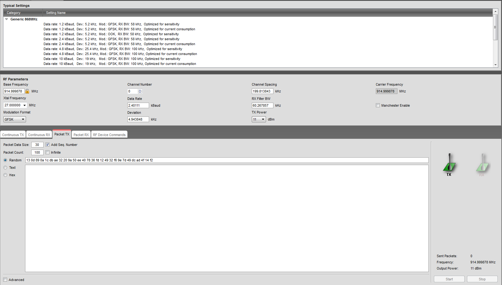
For our product, we are interfacing CC1350 to CC110L. Two such models are used, in which one can act as sub1 transmitter and other as sub1 receiver. I need CC1350 to act as RX and CC110L to act as TX. I am using  a datarate of 2.4 kbps, Deviation is 5, GFSK Modulation, 915 MHz Frequency. With SmartRF studio I generated the smartrfsettings files for both cc1350 and cc110L. Still I cannot receive any data on CC1350. What could I be possibly doing wrong?

I have attached the screenshots of both cc1350 and cc110l smartrf fields.

CC1350 Smart RF settings:

CC110L Smart RF settings:

Regards,

Anjaly

  • You need to make sure that the two devices uses the same sync word. T

    Siri
  • In addition, for CC1310, start from the legacy CC1101 settings. Also see www.ti.com/.../swra566.pdf
  • Upon searching I found. "CC1101 uses a 16 bit sync word that is repeated to generate a 32 bit sync word. On CC1310 the sync word then has to be set to 0xD391D391. "

    I followed this, still I couldn't receive any packets.
  • You have to describe in detail what your current setup is and how you derived the setting you use. You have not commented on the part with the datarate.

    As a sanity test, start with 38.4 kbps as described in dev.ti.com/.../cc1101-migration.html
  • Hi,

    What i have done actually is :

    i flashed the rfPacketRx project in my cc1350 module. Then I changed the smartrf settings in cc110l module and cc1350 module parameters exactly as told in the link (sync word also). But still I couldn't establish a communication. (The callback was not getting hit in the rx end in debugging mode ).

    I have another cc1350 module. I flashed the rfPacketTx project in that cc1350 module, and also used the same smartrf settings. Then communication was successfully happening. That is cc1350tx and cc1350rx.

    What could be the reason that CC110L Tx and CC1350Rx is not working. Any help will be appreciated,

  • Which link are you referring to? Could you do a code export from SmartRF Studio and post the exported code here?
  • You said that you first flashed the CC1350 with the rfPacketRX example and then you changes the settings?
    I assume you did the register changes in Studio first, then exported the settings to the rfPacketRX examples, re-built the project, and then flashed the device? Is that correct? Can you, as TER asked you to, please post the smartrf_settings.c file that you exported from Studio and used in the rfPacketRX example?
  • dev.ti.com/.../cc1101-migration.html

    This was the link i was referring
  • SmartRf settings of cc1350:

    // TI-RTOS RF Mode Object
    RF_Mode RF_prop =
    {
    .rfMode = RF_MODE_PROPRIETARY_SUB_1,
    .cpePatchFxn = &rf_patch_cpe_genfsk,
    .mcePatchFxn = 0,
    .rfePatchFxn = &rf_patch_rfe_genfsk,
    };

    // Overrides for CMD_PROP_RADIO_DIV_SETUP
    static uint32_t pOverrides[] =
    {
    // override_use_patch_prop_genfsk.xml
    // PHY: Use MCE ROM bank 4, RFE RAM patch
    MCE_RFE_OVERRIDE(0,4,0,1,0,0),
    // override_synth_prop_863_930_div5.xml
    // Synth: Set recommended RTRIM to 7
    HW_REG_OVERRIDE(0x4038,0x0037),
    // Synth: Set Fref to 4 MHz
    (uint32_t)0x000684A3,
    // Synth: Configure fine calibration setting
    HW_REG_OVERRIDE(0x4020,0x7F00),
    // Synth: Configure fine calibration setting
    HW_REG_OVERRIDE(0x4064,0x0040),
    // Synth: Configure fine calibration setting
    (uint32_t)0xB1070503,
    // Synth: Configure fine calibration setting
    (uint32_t)0x05330523,
    // Synth: Set loop bandwidth after lock to 20 kHz
    (uint32_t)0x0A480583,
    // Synth: Set loop bandwidth after lock to 20 kHz
    (uint32_t)0x7AB80603,
    // Synth: Configure VCO LDO (in ADI1, set VCOLDOCFG=0x9F to use voltage input reference)
    ADI_REG_OVERRIDE(1,4,0x9F),
    // Synth: Configure synth LDO (in ADI1, set SLDOCTL0.COMP_CAP=1)
    ADI_HALFREG_OVERRIDE(1,7,0x4,0x4),
    // Synth: Use 24 MHz XOSC as synth clock, enable extra PLL filtering
    (uint32_t)0x02010403,
    // Synth: Configure extra PLL filtering
    (uint32_t)0x00108463,
    // Synth: Increase synth programming timeout (0x04B0 RAT ticks = 300 us)
    (uint32_t)0x04B00243,
    // override_phy_rx_aaf_bw_0xd.xml
    // Rx: Set anti-aliasing filter bandwidth to 0xD (in ADI0, set IFAMPCTL3[7:4]=0xD)
    ADI_HALFREG_OVERRIDE(0,61,0xF,0xD),
    // override_phy_gfsk_rx.xml
    // Rx: Set LNA bias current trim offset to 3
    (uint32_t)0x00038883,
    // Rx: Freeze RSSI on sync found event
    HW_REG_OVERRIDE(0x6084,0x35F1),
    // override_phy_gfsk_pa_ramp_agc_reflevel_0x1a.xml
    // Tx: Enable PA ramping (0x41). Rx: Set AGC reference level to 0x1A.
    HW_REG_OVERRIDE(0x6088,0x411A),
    // Tx: Configure PA ramping setting
    HW_REG_OVERRIDE(0x608C,0x8213),
    // override_phy_rx_rssi_offset_5db.xml
    // Rx: Set RSSI offset to adjust reported RSSI by +5 dB
    (uint32_t)0x00FB88A3,
    // TX power override
    // Tx: Set PA trim to max (in ADI0, set PACTL0=0xF8)
    ADI_REG_OVERRIDE(0,12,0xF8),
    (uint32_t)0xFFFFFFFF,
    };


    // CMD_PROP_RADIO_DIV_SETUP
    rfc_CMD_PROP_RADIO_DIV_SETUP_t RF_cmdPropRadioDivSetup =
    {
    .commandNo = 0x3807,
    .status = 0x0000,
    .pNextOp = 0, // INSERT APPLICABLE POINTER: (uint8_t*)&xxx
    .startTime = 0x00000000,
    .startTrigger.triggerType = 0x0,
    .startTrigger.bEnaCmd = 0x0,
    .startTrigger.triggerNo = 0x0,
    .startTrigger.pastTrig = 0x0,
    .condition.rule = 0x1,
    .condition.nSkip = 0x0,
    .modulation.modType = 0x1,
    .modulation.deviation = 0x52,
    .symbolRate.preScale = 0x7,
    .symbolRate.rateWord = 0x2DE0,
    .rxBw = 0x24,
    .preamConf.nPreamBytes = 0x4,
    .preamConf.preamMode = 0x0,
    .formatConf.nSwBits = 0x20,
    .formatConf.bBitReversal = 0x0,
    .formatConf.bMsbFirst = 0x1,
    .formatConf.fecMode = 0x0,
    .formatConf.whitenMode = 0x0,
    .config.frontEndMode = 0x0,
    .config.biasMode = 0x1,
    .config.analogCfgMode = 0x0,
    .config.bNoFsPowerUp = 0x0,
    .txPower = 0xAB3F,
    .pRegOverride = pOverrides,
    .centerFreq = 0x0364,
    .intFreq = 0x8000,
    .loDivider = 0x05,
    };

    // CMD_FS
    rfc_CMD_FS_t RF_cmdFs =
    {
    .commandNo = 0x0803,
    .status = 0x0000,
    .pNextOp = 0, // INSERT APPLICABLE POINTER: (uint8_t*)&xxx
    .startTime = 0x00000000,
    .startTrigger.triggerType = 0x0,
    .startTrigger.bEnaCmd = 0x0,
    .startTrigger.triggerNo = 0x0,
    .startTrigger.pastTrig = 0x0,
    .condition.rule = 0x1,
    .condition.nSkip = 0x0,
    .frequency = 0x0364,
    .fractFreq = 0x0000,
    .synthConf.bTxMode = 0x0,
    .synthConf.refFreq = 0x0,
    .__dummy0 = 0x00,
    .__dummy1 = 0x00,
    .__dummy2 = 0x00,
    .__dummy3 = 0x0000,
    };

    // CMD_PROP_TX
    rfc_CMD_PROP_TX_t RF_cmdPropTx =
    {
    .commandNo = 0x3801,
    .status = 0x0000,
    .pNextOp = 0, // INSERT APPLICABLE POINTER: (uint8_t*)&xxx
    .startTime = 0x00000000,
    .startTrigger.triggerType = 0x0,
    .startTrigger.bEnaCmd = 0x0,
    .startTrigger.triggerNo = 0x0,
    .startTrigger.pastTrig = 0x0,
    .condition.rule = 0x1,
    .condition.nSkip = 0x0,
    .pktConf.bFsOff = 0x0,
    .pktConf.bUseCrc = 0x1,
    .pktConf.bVarLen = 0x1,
    .pktLen = 0x1E, // SET APPLICATION PAYLOAD LENGTH
    .syncWord = 0xD319D319,
    .pPkt = 0, // INSERT APPLICABLE POINTER: (uint8_t*)&xxx
    };

    // CMD_PROP_RX
    rfc_CMD_PROP_RX_t RF_cmdPropRx =
    {
    .commandNo = 0x3802,
    .status = 0x0000,
    .pNextOp = 0, // INSERT APPLICABLE POINTER: (uint8_t*)&xxx
    .startTime = 0x00000000,
    .startTrigger.triggerType = 0x0,
    .startTrigger.bEnaCmd = 0x0,
    .startTrigger.triggerNo = 0x0,
    .startTrigger.pastTrig = 0x0,
    .condition.rule = 0x1,
    .condition.nSkip = 0x0,
    .pktConf.bFsOff = 0x0,
    .pktConf.bRepeatOk = 0x0,
    .pktConf.bRepeatNok = 0x0,
    .pktConf.bUseCrc = 0x1,
    .pktConf.bVarLen = 0x1,
    .pktConf.bChkAddress = 0x0,
    .pktConf.endType = 0x0,
    .pktConf.filterOp = 0x0,
    .rxConf.bAutoFlushIgnored = 0x0,
    .rxConf.bAutoFlushCrcErr = 0x0,
    .rxConf.bIncludeHdr = 0x1,
    .rxConf.bIncludeCrc = 0x0,
    .rxConf.bAppendRssi = 0x0,
    .rxConf.bAppendTimestamp = 0x0,
    .rxConf.bAppendStatus = 0x1,
    .syncWord = 0xD319D319,
    .maxPktLen = 0xFF, // MAKE SURE DATA ENTRY IS LARGE ENOUGH
    .address0 = 0xAA,
    .address1 = 0xBB,
    .endTrigger.triggerType = 0x1,
    .endTrigger.bEnaCmd = 0x0,
    .endTrigger.triggerNo = 0x0,
    .endTrigger.pastTrig = 0x0,
    .endTime = 0x00000000,
    .pQueue = 0, // INSERT APPLICABLE POINTER: (dataQueue_t*)&xxx
    .pOutput = 0, // INSERT APPLICABLE POINTER: (uint8_t*)&xxx
    };

    SmartRF register settings of CC110l:

      {CC110L_IOCFG0,           0x06},

      {CC110L_FIFOTHR,          0x47},

      {CC110L_SYNC1,            0xD3},

      {CC110L_SYNC0,            0x19},

      {CC110L_PKTLEN,           0xFF},

      {CC110L_PKTCTRL1,         0x04},

      {CC110L_PKTCTRL0,         0x05},

      {CC110L_ADDR,             0x00},

      {CC110L_CHANNR,           0x00},

      {CC110L_FSCTRL1,          0x06},

      {CC110L_FSCTRL0,          0x00},

      {CC110L_FREQ2,            0x20},

      {CC110L_FREQ1,            0x25},

      {CC110L_FREQ0,            0xED},

      {CC110L_MDMCFG4,          0xCA},

      {CC110L_MDMCFG3,          0x75},

      {CC110L_MDMCFG2,          0x13},

      {CC110L_MDMCFG1,          0x22},

      {CC110L_MDMCFG0,          0xE5},

      {CC110L_DEVIATN,          0x34},

      {CC110L_MCSM2,            0x07},

      {CC110L_MCSM1,            0x30},//0x30//0x3F

      {CC110L_MCSM0,            0x18},

      {CC110L_FOCCFG,           0x16},

      {CC110L_BSCFG,            0x6C},

      {CC110L_AGCCTRL2,         0x43},

      {CC110L_AGCCTRL1,         0x40},

      {CC110L_AGCCTRL0,         0x91},

      {CC110L_FREND1,           0x56},

      {CC110L_FREND0,           0x10},

      {CC110L_FSCAL3,           0xE9},

      {CC110L_FSCAL2,           0x2A},

      {CC110L_FSCAL1,           0x00},

      {CC110L_FSCAL0,           0x1F},

      {CC110L_TEST2,            0x81},

      {CC110L_TEST1,            0x35},

      {CC110L_TEST0,            0x09},

      {CC110L_PA_TABLE0,        0xC0}

  • It could look like you have not followed the step by step in 2.7.1 in www.ti.com/.../swra566.pdf on the CC1350 side.
  • Hi,

    I am new in working with smartrf. Can you please explain to me what all override settings I should change?

  • This should be covered in the app note I have pointed you to.