This thread has been locked.

If you have a related question, please click the "Ask a related question" button in the top right corner. The newly created question will be automatically linked to this question.

Compiler/CC1120: CC1120 920M Matching Network

Part Number: CC1120
Other Parts Discussed in Thread: CC1190,

Tool/software: TI C/C++ Compiler

HI

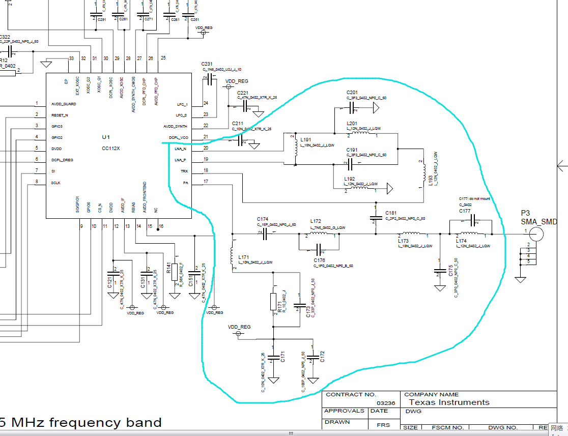
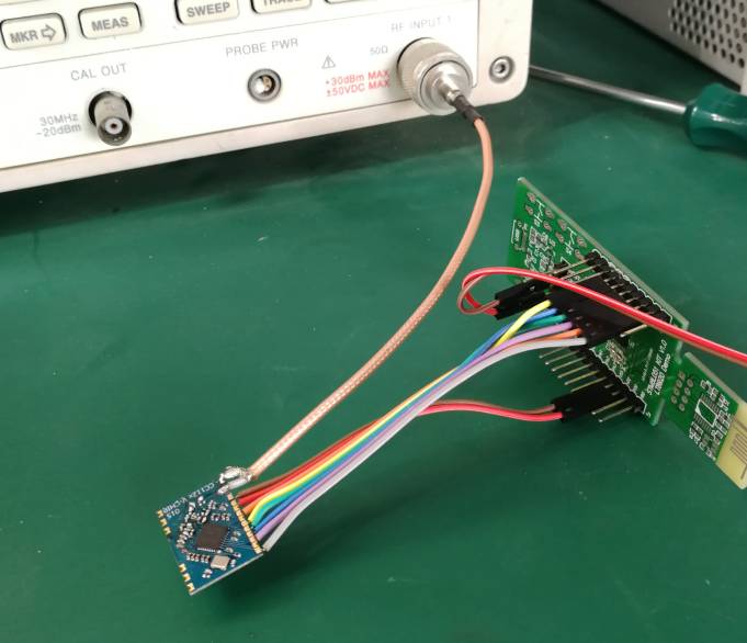
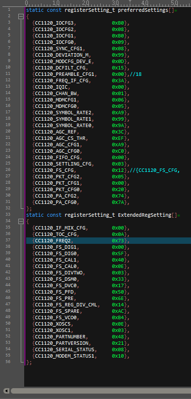
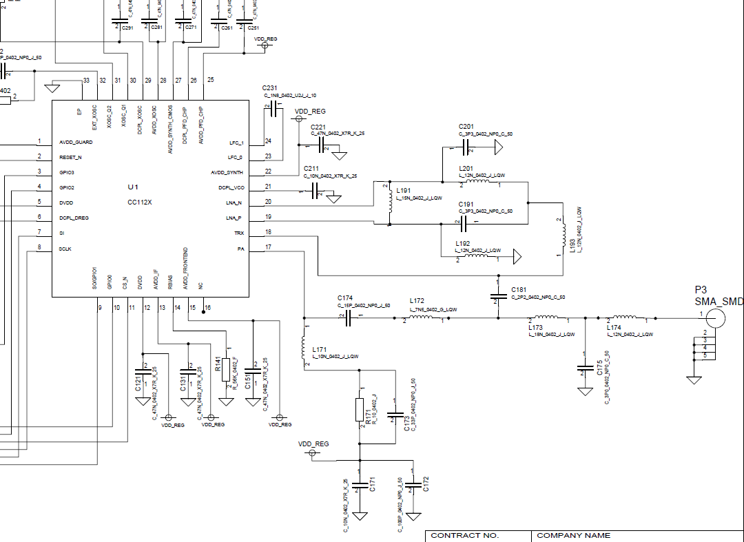
I use the 1120 RF chip and want it to run in the 920M band.
I am currently struggling to find relevant reference circuits, especially matching networks.
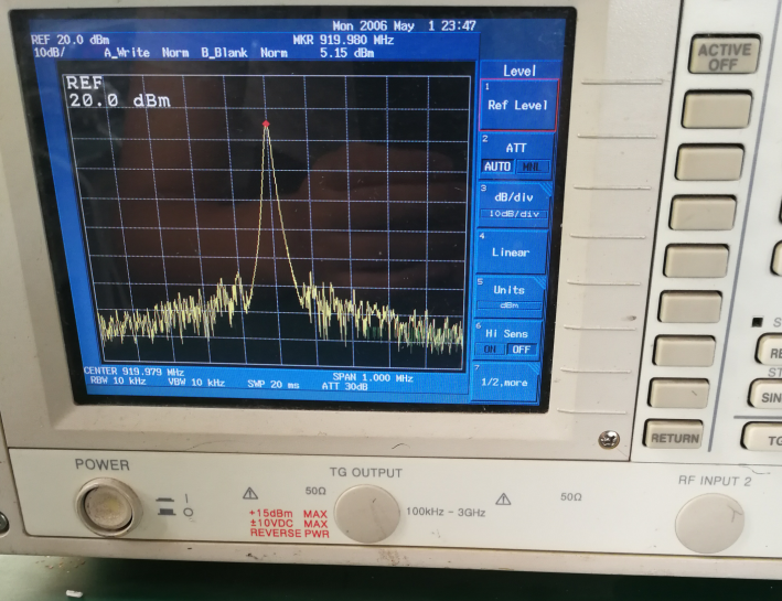
I used a 915M circuit and measured antenna radiated power at only 5dBm when I configured it to 10dBm.

Where can I find these reference files, please?


TKS 

  • It sounds like you have used the correct reference design.
    - Have you measured the conducted output power?
    - Which antenna do you use?
    - Is it tuned for your board?
    - How have you measured radiated power?
  • I used the matching parameters of CC1120+CC1190. I'm sure this is not a good choice. All I expect is to use only CC1120.
    The measurement method is to use a spectrum analyzer to measure the power at the antenna entrance in the case of continuous transmission of the preamble
  • "I used the matching parameters of CC1120+CC1190. I'm sure this is not a good choice. All I expect is to use only CC1120."
    Are you here referring to the antenna match?
    "The measurement method is to use a spectrum analyzer to measure the power at the antenna entrance in the case of continuous transmission of the preamble"
    Is this conducted or radiated? And why use preamble and not a CW?

    I need answers to the following to be able to help:
    - Have you measured the conducted output power?
    - Which antenna do you use?
    - Is it tuned for your board?
    - How have you measured radiated power?
  • --I use a spring antenna

    --I removed the spring antenna and measured the power at the entrance of the antenna when continuously transmitting the carrier.

    The power at only 5dBm when I configured it to 10dBm.

    What I most want to understand is the reference circuit and parameters when the system is operating at 920MHZ.

    The section marked below

  • In your first post you wrote that you measured 5 dBm radiated but in reality it's a conducted measurement.

    The match shown in the picture is a broad band match that gives good performance up to 930 MHz. If you get 5 dBm if you have programmed the chip to use the 10 dBm setting indicate that your design deviate from our ref design.

    - Have you tested the output power for other output power settings?
    - Could you post a picture showing how you connect the DUT to the spectrum for the measurements you have done?
  •  

    The following figure is the relevant test chart and register parameter configuration.

    Hope can help you quickly find the problem.

    Do you have a 920M reference application circuit?I can use it to re-test it and compare it with the original design. 


  • Could you share the schematic (pdf) , BOM file and layout (gerber)? If you don't want it public on the forum you can send me a friend request and that way send it directly to me.
  •  

    My design is designed according to the following reference document, including the schematic and BOM.

    I used this reference circuit because I did not find the 920M reference design.

    It is because I used the following incorrect reference circuit, so I expect to get the correct reference circuit. Thank.

    What I want to know most is the 920M reference design document. So I hope you can directly provide 920M reference documents.

  • As I have replied before, www.ti.com/.../tidr240.pdf also cover 920 MHz.

    You are measuring 5 dBm output power indicating that something is done wrong. From the picture you posted it's not easy to see exactly where you have soldered on the semi rigid cable but from what I could see this looks correct. That leaves the schematic, BOM or layout. For the later, the picture indicate that you are not following the layout part of the ref design. I have also seen a lot of designs where the customer has claimed that the reference design is followed and I find out that that is not the case. It could also be assemble errors, it happens now and again that the assembly house mount a different value than stated in the BOM list.