This thread has been locked.

If you have a related question, please click the "Ask a related question" button in the top right corner. The newly created question will be automatically linked to this question.

CC1310: SPI Configuration Issue

Part Number: CC1310

Hi,

  I am trying to connect an ST Micro accelerometer (LSM6DSM) to the 1310.  The problem I am seeing is that the command gets clocked

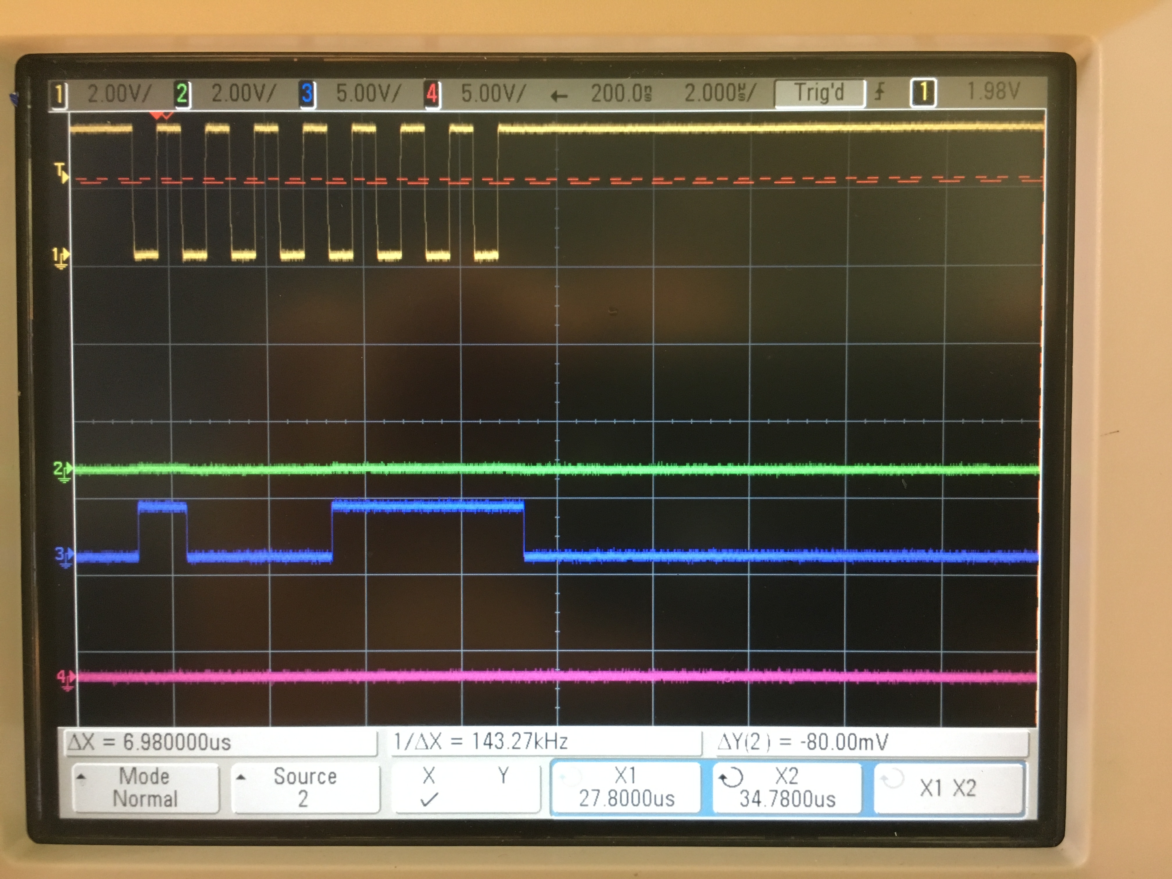
out by the master (1310) but I never see the clocks provided to the slave for it to clock it's response back. Here is a shot of the scope

trace showing the command 0x8F being sent to the accelerometer but no clocks to return the response which should happen immediately

after the command is sent.  You can see the 8 clocks for the command itself.  There should be 8 more clocks allowing the accelerometer

to respond on the MISO (pink trace).  The chip select (green trace) for the accelerometer is tied low.  The blue trace is data and the yellow

is the clock coming from the 1310.

I used the lcd display example code as a starting point.  The SPI initialization code looks like this:

    /* Open SPI as master (default) */
    SPI_Params_init(&spiParams);
    spiParams.frameFormat = SPI_POL1_PHA1;
    spiParams.dataSize = 8;
    masterSpi = SPI_open(Board_SPI_MASTER, &spiParams);
    if (masterSpi == NULL) {
        printf("Error initializing master SPI\n");
        while (1);
    }
    else {
        printf("Master SPI initialized\n");
    }

The polarity and phase were selected based on the datasheet for the accelerometer.

I looked in the 1310 reference manual and did not see anything that enable/disable the clocks for the incoming slave->master response.

The accelerometer does not support master/slave negotiation so I just commented-out that part of the initialization. Is there some other

initialization I need to do in order to force the 1310 to be the master?


Victor

  • Hi Victor,

    How do you perform you SPI transaction in code? I would expect you to setup a 2 byte transfer in the scenario you are describing but it sounds like you might just setup a 1 byte transaction.
  • Here is the code I am using to read from a SPI device.  The command to the slave is 8-bits and and the response is

    also 8-bits.

    int32_t spi_read(void *handle, uint8_t reg, uint8_t *data, uint16_t len)
    {
    SPI_Transaction transaction;
    uint16_t readTmp;
    uint8_t cmd = reg | 0x80;     // set the command bit to the accel

    transaction.count = 1;
    transaction.txBuf = (void *)&cmd;
    transaction.rxBuf = (void *)&readTmp;

    SPI_transfer(masterSpi, &transaction);

    return(0);
    }

    I have tried changing the transaction count to 2 but it behaves the same way.  I have also tried adding a second call to SPI_Transfer()

    but it looks just like the first one with no data clocked back.

    Victor

  • One additional note....

    I believe that I may have the mode set incorrectly.  I think what I really want is SPI_MW which is the National Microwire format.  In the 1310 reference

    manual this most closely matches the bus behavior the accelerometer is expecting.

    From the 1310 reference manual:

    I've tried this and it's still not working correctly but I believe it is closer.

    Victor

  • Hi Victor,

    Looking at the LSM datasheet, I would say you should use the Motorola frame format with SPO = 1 and SPH = 1 (see the technical reference manual page 1493).

    At page 45 in the LSM datasheet you can see how the SPI read operation should look. This means that you will have transfer two bytes in order to read out the value of a register. Based on this I would structure the transaction buffer like this:

    SPI_Transaction transaction;
    uint8_t readTmp[2] = {0};
    uint8_t cmd[2] = { (reg | 0x80), 0 }; // set the command bit to the accel


    transaction.count = 2;
    transaction.txBuf = (void *)&cmd;
    transaction.rxBuf = (void *)&readTmp;

    SPI_transfer(masterSpi, &transaction);

    *data = readTmp[1]; // <- First byte is (should be) "trash"

  • Hi M-W

      Thanks for helping me out with this issue.  I agree with using the Motorola frame format.

    Here is the my test code based on your suggestion:

    // Init

    SPI_Params_init(&spiParams);
    spiParams.frameFormat = SPI_POL1_PHA1;
    spiParams.dataSize = 8;
    masterSpi = SPI_open(Board_SPI_MASTER, &spiParams);

    // read

    SPI_Transaction transaction;
    uint8_t readTmp[2] = {0};
    uint8_t cmd[2] = { (reg | 0x80), 0 };

    transaction.count = 2;
    transaction.txBuf = (void *)&cmd;
    transaction.rxBuf = (void *)&readTmp;

    SPI_transfer(masterSpi, &transaction);

    *data = readTmp[1];

    Unfortunately it's still returning 0 for the device id.  I tried all combinations of spi mode 0, 3 and 5 and datasizes of 8 and 16 bits

    and transfer sizes of 1 and 2 bytes.  Unfortunately I don't have access to a scope at this time so it's hard to see exactly

    what is happening.

    I am going to go through the wiring carefully today to see if something is wrong.

    Victor

  • Hi Victor,

    Now the code snippet looks ok to me at least. Let me know if you find something out with the hardware/wiring itself.

    If you could get you hand on a scope that would be great, it is really hard to tell what might be wrong without seeing the line activity.