This thread has been locked.

If you have a related question, please click the "Ask a related question" button in the top right corner. The newly created question will be automatically linked to this question.

CC1310: DCDC frequency on custom board - Problem with low power standby current

Part Number: CC1310

Following my last post, I'm designing a wireless sensor powered by energy harvesting. So low current consumption is a must.

I successfully designed a prototype board with similar measurements compared to LP. Reaching something around 3uA in standby.

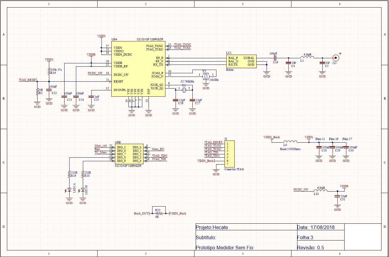
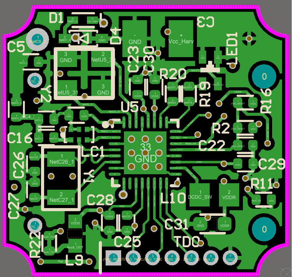
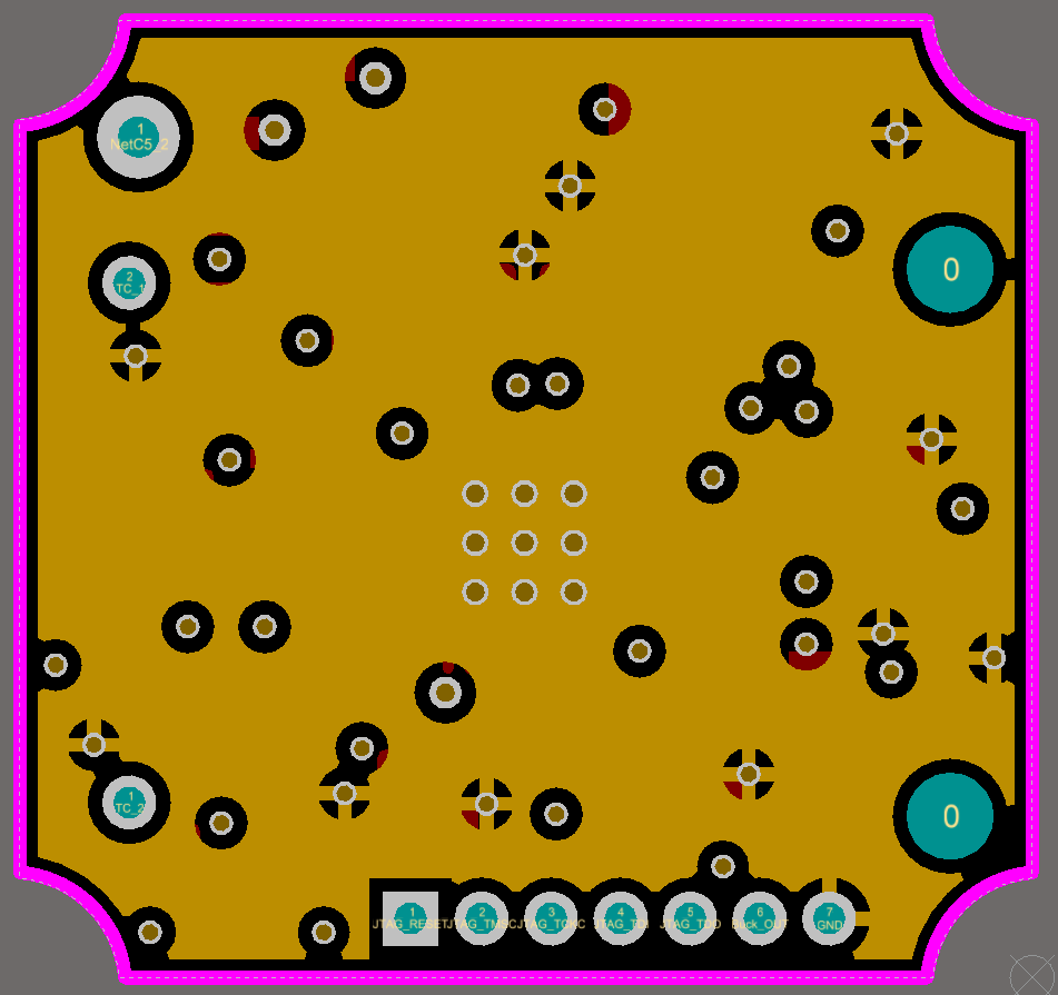
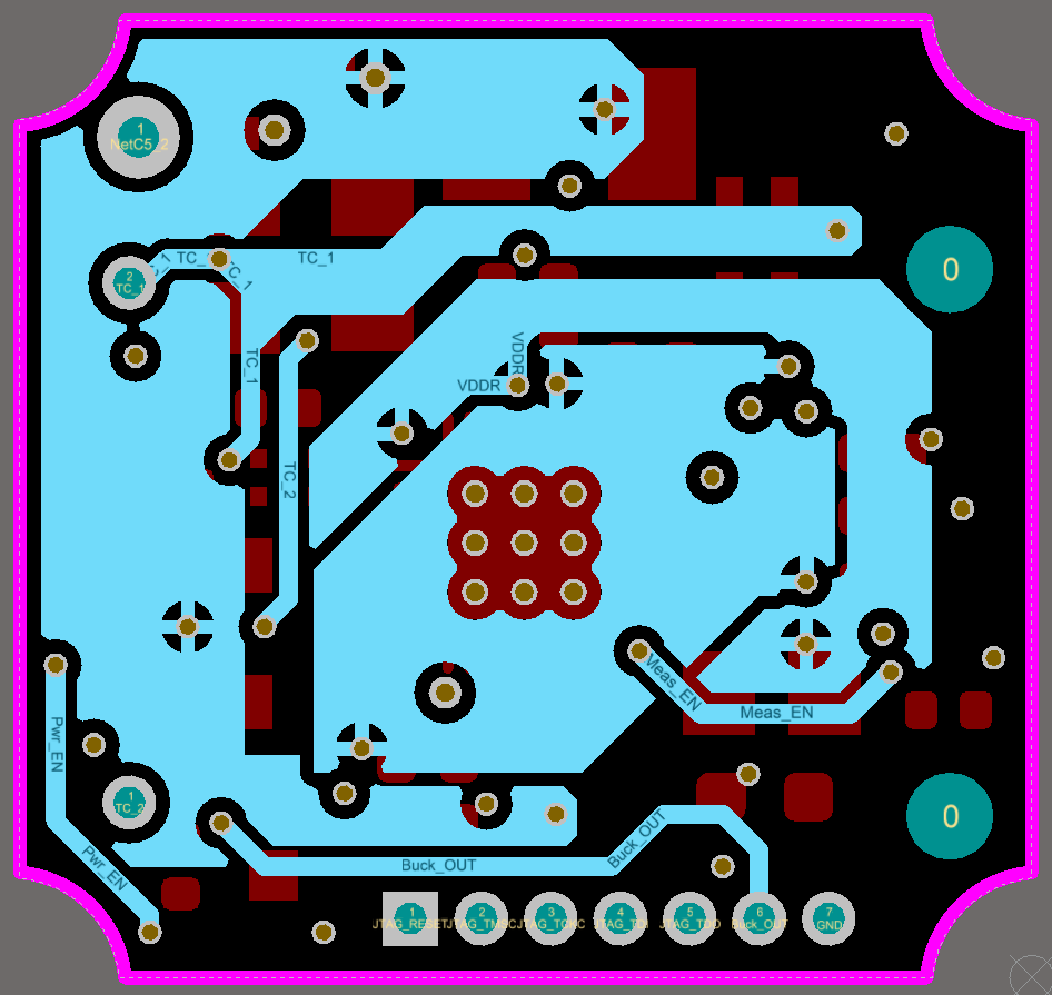
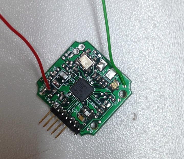
The problem is with my miniature board...  It was designed from the same schematic as my prototype board, but in a much smaller 4 layers PCB.
I'm using the same  part number for all critical components (the same from the reference LP design). But consumption is about 600uA.

I'm totally lost here.
The firmware is exactly the same. Schematic has only small differences on DIO, but I unmounted any components connected to CC1310, making both boards virtually the same.
Layout is obvious different but, theoretically, it was better designed in the miniature version.

I've already tried to swap the CC1310 from both boards, but nothing happened.

I've just found a big difference on the signal of DCDC_SW pin.
- On the LP, I measured a sawtooth-like signal of really low frequency, of about ~1Hz. I'm assuming this is the ideal case.
- On my prototype board, I've got also a sawtooth-like signal, but with frequency of about 50Hz.
- On my miniature board, switching is happening so fast that I cannot see the sawtooth, but voltage after the inductor looks beautifully plain, at 1,67V.

I've tried to disable the DCDC from ccfg.
In this configuration, current raised to about 900uA in the miniature board and to about 150uA on the prototype.

Anyone has any idea to what might be happening?
I'm almost calling for black magic (just kidding).

  • Thiago,

    Can you post the schematic publicly? If so, please do.

    I think you are getting close, from your testing you have found the SAW tooth signal on the DCDC converter is not the same on the boards. The way the SAW tooth signal is generated is that the device has a voltage comparitor built in and when this comparitor detects the voltage goes below a certain threshold it will automatically call for a DCDC converter pulses, this is fully automatic and therefore the reason you see the difference is that your boards have different sleep currents and the chip is automatically adapting to this.

    Getting leakage currents to be below 1uA is actually quite difficult and assuming the software is the same between the three tests, here are some things to look for.

    • Make sure the schematic is the same, for example, look for that there is no 100K or 1M resistors being held high or low by the device during sleep.
    • Decoupling (all of them) capacitors of different brands will behave differently, we chose the ones on reference design carefully.
    • Flux residue is conductive, so make sure you clean you boards vigorously. 

    Regards,
    /TA

  • Dear TA12012,

    Thank you for those precious information!

    Right now I'm on my personal computer and tomorrow  is holiday here in Brazil (Independence Day), so I will get back to work only Monday.
    Monday morning I post the schematic and check all decoupling capacitors.
    Each PCB were assembled about 3 months apart, so probably the capacitors might be of different brands.


    BR,

  • Dear TA12012,

    Follows the schematic of both boards.
    The miniature version, that has the high current problem, is the one with just 2 LEDs connected to GPIO PINs.

    Apart from the LEDs and TDO/TDI pins, I have unmounted any connection to GPIOs on both boards. So DIOs 5,6,7 and 9 are floating.
    Balun is also unmounted on the miniature versions.

    L9, L10, Y1 and Y2 are the same part numbers as reference design from TI.
    CC1310 part number is actually notated wrong in this schematic as I'm using RSM (4x4) version.

    I'm just cleaned the board with proper PCB cleaner product to remove any flux residue. But the consumption remains the same....
    I'll try now changing all decoupling capacitors.

    Any news, I'll post here.

    BR,

  • Your schematics look good, but your comment about removing the nodes reminded me of an other item to check for.

    Its very important that you initialize all your IO to something that makes sense, the trick is that even if a node is left floating and the CC device is configured as an input for that pin, then the pin could float to somewhere between 0 and 1 that is not defined and the CC will start to draw tens of microamps in that port.

    Regards,
    /TA
  • Hello,

    In order to avoid any type of leakage current on a GPIO, I recommend initializing all pins to:

    | PIN_GPIO_OUTPUT_DIS | PIN_INPUT_DIS | PIN_GPIO_LOW | PIN_PUSHPULL |PIN_NOPULL | PIN_DRVSTR_MIN

    This will leave the pin in a High-Z state in which current will not flow through it.

    Regards,

    AB

  • From 11.6 in www.ti.com/.../swcu117h.pdf: "By default, the I/O driver (output) and input buffer (input) are disabled (tri-state mode) at power on or reset, and thus the I/O pin can safely be left unconnected (floating)."
  • Hello guys,

    Yesterday I followed all tips but problem persists.
    I've set PIN initialization to the one recommended by AB and changed all capacitors from both PCBs, but behaviour remains the same....

    While testing the prototype board I was using as reference I did some mistake that spoiled the uC....
    I will assembly a new PCB and check if I get a different behaviour.

    EDIT: Forgot to ask.
    Is there any possible way that some hardware configuration is preventing software to enter Standby and hold system on Idle?

    BR

  • Does the schematic show the full circuit since I see some DIOs have a name that looks like is nowhere else on the schematic.
  • Hello TER,

    As I said to TA12012, I disassembled any GPIO connection for this tests, except from the LEDs and TDO/TDI pins.
  • Sorry, overlooked that for a second. But the current consumption indicate that you have something that is undefined. Since you have removed components, have you remembered to redefine these DIOs?
  • Hello TER,

    I've set every pin to the default configuration recommended by AB.
    Here is my initialization code:

    #include <stdint.h>
    #include <stddef.h>
    
    #include <NoRTOS.h>
    #include <ti/drivers/Power.h>
    
    /* Example/Board Header files */
    #include "Board.h"
    
    const PIN_Config BoardGpioInit[] = {
    
        IOID_0    | PIN_GPIO_OUTPUT_DIS | PIN_INPUT_DIS | PIN_GPIO_LOW | PIN_PUSHPULL |PIN_NOPULL | PIN_DRVSTR_MIN,
        IOID_1    | PIN_GPIO_OUTPUT_DIS | PIN_INPUT_DIS | PIN_GPIO_LOW | PIN_PUSHPULL |PIN_NOPULL | PIN_DRVSTR_MIN,
        IOID_2    | PIN_GPIO_OUTPUT_DIS | PIN_INPUT_DIS | PIN_GPIO_LOW | PIN_PUSHPULL |PIN_NOPULL | PIN_DRVSTR_MIN,
        IOID_3    | PIN_GPIO_OUTPUT_DIS | PIN_INPUT_DIS | PIN_GPIO_LOW | PIN_PUSHPULL |PIN_NOPULL | PIN_DRVSTR_MIN,
        IOID_4    | PIN_GPIO_OUTPUT_DIS | PIN_INPUT_DIS | PIN_GPIO_LOW | PIN_PUSHPULL |PIN_NOPULL | PIN_DRVSTR_MIN,
        IOID_5    | PIN_GPIO_OUTPUT_DIS | PIN_INPUT_DIS | PIN_GPIO_LOW | PIN_PUSHPULL |PIN_NOPULL | PIN_DRVSTR_MIN,
        IOID_6    | PIN_GPIO_OUTPUT_DIS | PIN_INPUT_DIS | PIN_GPIO_LOW | PIN_PUSHPULL |PIN_NOPULL | PIN_DRVSTR_MIN,
        IOID_7    | PIN_GPIO_OUTPUT_DIS | PIN_INPUT_DIS | PIN_GPIO_LOW | PIN_PUSHPULL |PIN_NOPULL | PIN_DRVSTR_MIN,
        IOID_8    | PIN_GPIO_OUTPUT_DIS | PIN_INPUT_DIS | PIN_GPIO_LOW | PIN_PUSHPULL |PIN_NOPULL | PIN_DRVSTR_MIN,
        IOID_9    | PIN_GPIO_OUTPUT_DIS | PIN_INPUT_DIS | PIN_GPIO_LOW | PIN_PUSHPULL |PIN_NOPULL | PIN_DRVSTR_MIN,
        PIN_TERMINATE
    };
    
    extern void *mainThread(void *arg0);
    
    /*
     *  ======== main ========
     */
    int main(void)
    {
        /* Call driver init functions */
        Power_init();
    
        if (PIN_init(BoardGpioInit) != PIN_SUCCESS) {
            /* Error with PIN_init */
            while (1);
        }
    
        /* Start NoRTOS */
        NoRTOS_start();
    
        /* Call mainThread function */
        mainThread(NULL);
    
        while (1);
    }

    And the mainThread:

    #include <unistd.h>
    
    /* Driver Header files */
    #include <ti/drivers/PIN.h>
    #include <ti/drivers/pin/PINCC26XX.h>
    
    /* Example/Board Header files */
    #include "Board.h"
    
    /* Led pin table */
    PIN_Config LedPinTable[] =
    {
        IOID_8    | PIN_GPIO_OUTPUT_EN | PIN_GPIO_LOW | PIN_PUSHPULL | PIN_DRVSTR_MAX, /* LED initially off */
        IOID_9    | PIN_GPIO_OUTPUT_EN | PIN_GPIO_LOW | PIN_PUSHPULL | PIN_DRVSTR_MAX, /* LED initially off */
        PIN_TERMINATE                                                                      /* Terminate list */
    };
    
    /*
     *  ======== mainThread ========
     */
    void *mainThread(void *arg0)
    {
        PIN_State   pinState;
        PIN_Handle  hPin;
        uint32_t    currentOutputVal;
        uint32_t    standbyDuration = 5000000;
    
        /* Allocate LED pins */
        hPin = PIN_open(&pinState, LedPinTable);
    
        /*
         * Repeatedly sleeps for a duration, to allow repeated entry/exit
         * from standby. The LED states are toggled on each iteration
         */
    //    PIN_setPortOutputValue(hPin, 1);
        while(1) {
            /* Sleep, to let the power policy transition the device to standby */
            usleep(standbyDuration);
    
            /* Read current output value for all pins */
            currentOutputVal =  PIN_getPortOutputValue(hPin);
    
            /* Toggle the LEDs, configuring all LEDs at once */
            PIN_setPortOutputValue(hPin, ~currentOutputVal);
        }
    }
    

  • Still lost here...

    Due to supplier reasons we will exchange CC1310 version from RSM to RHB.
    So I'll design a new version of the PCB for the RHB version and hope that my problem is from PCB defectuous manufacture.

    Anyone here would mind checking my layout?
    It is a 4-layer PCB, but I'm posting only the ones directly related to the CC1310.


  • Can you post a picture of the device that you are testing on.

    The layout does not follow our recommendations, it would take a pretty close review of Gerber files to make any conclusions.

    Can you post the Gerber files in a zip?

    Regards,
    /TA
  • Hello TA12012.

    Here is the device:

    Would you mind if I send you the gerber privately?

    BR