This thread has been locked.

If you have a related question, please click the "Ask a related question" button in the top right corner. The newly created question will be automatically linked to this question.

CC1310: Read sensor value through UART TXD RXD pins

Part Number: CC1310

Hi guys,

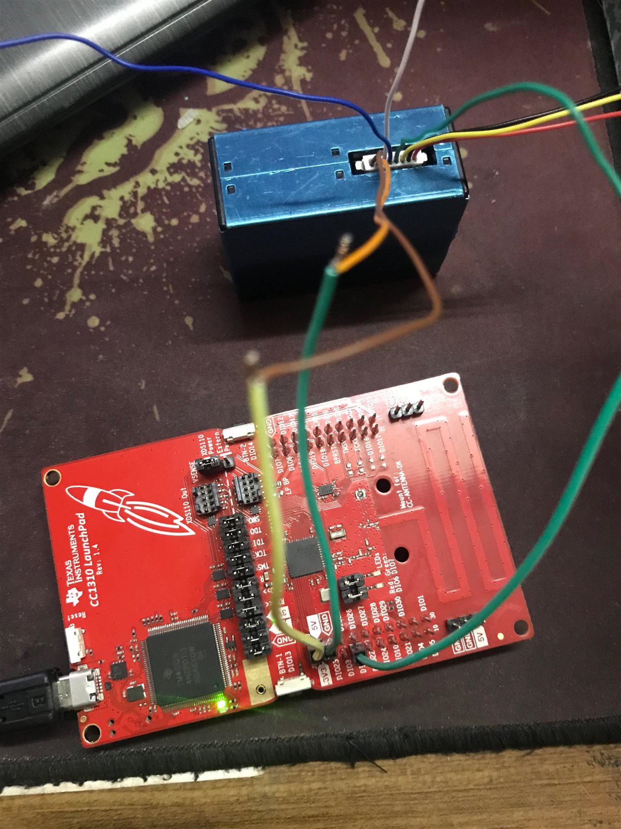
I tend to use the Plantower PM2.5 PMS5003 dust sensor. This sensor outputs value through UART pins. I attached it to TXD and RXD of the CC1310 Launchpad but I still do not know how to use these pins.

Does anyone know how to use these pins or have any documents about URAT pins of the launchpad?

  • Could you post a picture of how you connect this? (clearly showing where everything is connected)
  • Hi TER, thanks for replying.

    I would like to describe it clearer:

    I connected VCC and GND to 5V pin and GND of the launchpad, the TX pin of the sensor to DIO2(RXD) pin of the launchpad

    And I want to read only values from this pin and print it out.

  • Now you are trying to drive the UART both from the sensor and the XDS110. I would start trying to remove the RXD/ TXD jumpers.
  • I removed them.
    I have read the UART.h header and uartecho example
    I am confused about uart = UART_open(Board_UART0, &uartParams);
    Is it the command to open DIO2 pin and ready for receive data?
    And UART_write(uart, echoPrompt, sizeof(echoPrompt));
    What is this command used for?
  • Yes, UART_open is the API to open UART pins ready for receive and transmit data. UART_write is to send data to UART TX pin.
  • Did you see any change when you removed the jumpers?
  • Make sure you have the Baudrates set the same.
  • I can't get the result, here is my code after editting

    #include <stdint.h>
    #include <stddef.h>

    /* Driver Header files */
    #include <ti/drivers/GPIO.h>
    #include <ti/drivers/UART.h>
    #include <ti/display/Display.h>

    /* Example/Board Header files */
    #include "Board.h"

    /*
    * ======== mainThread ========
    */
    void *mainThread(void *arg0)
    {
    uint16_t output;
    uint8_t buffer[32];
    //const char echoPrompt[] = "Echoing characters:\r\n";
    UART_Handle uart;
    UART_Params uartParams;

    /* Call driver init functions */
    GPIO_init();
    UART_init();

    Display_Handle displayHandle;
    Display_Params displayParams;
    Display_Params_init(&displayParams);
    displayHandle = Display_open(Display_Type_UART, NULL);


    /* Configure the LED pin */
    GPIO_setConfig(Board_GPIO_LED0, GPIO_CFG_OUT_STD | GPIO_CFG_OUT_LOW);

    /* Turn on user LED */
    GPIO_write(Board_GPIO_LED0, Board_GPIO_LED_ON);

    /* Create a UART with data processing off. */
    UART_Params_init(&uartParams);
    uartParams.writeDataMode = UART_DATA_BINARY;
    uartParams.readDataMode = UART_DATA_BINARY;
    uartParams.readReturnMode = UART_RETURN_FULL;
    uartParams.baudRate = 9600;

    uart = UART_open(Board_UART0, &uartParams);

    if (uart == NULL) {
    /* UART_open() failed */
    while (1);
    }

    //UART_write(uart, echoPrompt, sizeof(echoPrompt));

    /* Loop forever echoing */
    while (1) {
    UART_read(uart, &buffer,sizeof(buffer));
    Display_printf(displayHandle, 1, 0,"Output: %d",buffer);
    }
    }

    I am trying to write results into parameter buffer and print it out

  • Hi TER
    When I remove the RXD and TXD jumper, I get nothing. But when I connect TXD jumper again, the UART_open() is failed.
  • In the case where you remove the jumpers, have you monitored the lines with a oscilloscope to see if something is happening? I assume that you have set the SET line to high (3.3 V).
  • Sorry, I don't have the oscilloscope to test.
    My sensor doesn't need to be set the SET line, it will send serial output to the host automatically after powering up.
    Moreover, I have done the UARTecho example with 2 launchpads interacted with each other. And I only sent input when 2 jumpers are connected. When I removed them, nothing happens.
  • I would suggest you to make sure UARTecho example works on your LAUNCHXL-CC1310 first and do porting to work with PMS5003 after that.
  • Sang Tran Phuc: "Moreover, I have done the UARTecho example with 2 launchpads interacted with each other": The UART echo uses input from the keyboard, if you use the example between two LPs, which LP is actually providing input for the other since both will just wait for input.

    Also, for this sort of debugging you need a scope or a logic analyzer to see if you get anything on the lines.
  • When I tested UARTecho example with 2 launchpads (with jumpers connected), I used input from keyboard of the terminal of first launchpad and the results appeared in the second terminal and vice versa.
  • According to your picture showing connection between PMS5003 and CC1310, I suspect you don’t connect UART connection and all other pins correctly.
  • Hi YK,
    I don't know there are differences between the UART connection of CC1310 LP and Arduino. But I just need 3 connection in Arduino to read the sensor value, there are VCC, GND and TX pins.
    I also tried UARTecho example with one LP. I use CCS terminal to turn on the serial of the LP. When I launched the LP, the "Echoing characters:" appreared and I type some words from keyboard and these words were shown in the serial session. Am I doing correctly?
  • I think you should connect at least 4 pins, VCC, GND, TX, and RX. If you don’t connect RX Pin, it doesn’t work.
  • As said the uartecho example is for typing a char on the keyboard and display this on the display. UART is basically between 2 units, if you leave the jumpers on and have two LPs you have 3 units which could work fine if TXD is connected to 2 RXD pins but the other way won't work.

  • Hi guys,

    I leave the TXD jumper on and remove the RXD jumper, and I have some strange characters appearing on the terminal. I think those are signal from the sensor. Here is my code

    void *mainThread(void *arg0)
    {
    uint8_t buffer[32];
    const char echoPrompt[] = "Output:\r\n";
    UART_Handle uart;
    UART_Params uartParams;

    /* Call driver init functions */
    GPIO_init();
    UART_init();


    /* Configure the LED pin */
    GPIO_setConfig(Board_GPIO_LED0, GPIO_CFG_OUT_STD | GPIO_CFG_OUT_LOW);

    /* Turn on user LED */
    GPIO_write(Board_GPIO_LED0, Board_GPIO_LED_ON);

    /* Create a UART with data processing off. */
    UART_Params_init(&uartParams);
    uartParams.writeDataMode = UART_DATA_BINARY;
    uartParams.readDataMode = UART_DATA_BINARY;
    uartParams.readReturnMode = UART_RETURN_FULL;
    uartParams.readEcho = UART_ECHO_OFF;
    uartParams.baudRate = 9600;

    uart = UART_open(Board_UART0, &uartParams);

    if (uart == NULL) {
    /* UART_open() failed */
    while (1);
    }

    UART_write(uart, echoPrompt, sizeof(echoPrompt));

    /* Loop forever echoing */
    while (1) {

    UART_read(uart, &buffer, sizeof(buffer));
    UART_write(uart, &buffer,sizeof(buffer));
    }
    }

    How can I see these output clearer?

    The baud rate of the sensor is 9600.

  • I suggest you to use a terminal tool that can display this UART in hex format to read what you received on your CC1310.
  • Hi YK,
    Can I use other ways to demonstrate the received signal instead of using UART_write to write out the terminal?
    I tried displayHandle = Display_open(Display_Type_UART, NULL); and Display_printf but this will make the UART_open() fail and only works when baud rate is 115200 which is different from sensor's baud rate.

  • I finally understand what you mean to do. I suppose you connect PMS5003 UART TX to LAUNCHXL-CC1310 UART RX (DIO_02) to receive data from PMS5003 so you have to remove RX jumper between XDS110 Debugger and CC1310 on LaunchPad. You need to keep TX jumper unremoved so you can use UART_write to output received data from PMS5003 to LaunchPad virtual COM port. I suppose the data is in hex format so you should use some terminal tool that can display received data in hex format to check what you received from PMS5003.
  • Hi YK,

    Sorry for late update.

    I have succeeded in reading and showing this sensor value. But now I am stuck when trying to convert data from UART port to decimal values and combining this project to a big project like Sensor and Collector example. I found out that the Sensor and Collector example using baud rate 115200 but the baud rate of the sensor is 9600 so that I cannot print out its values.

    How can I fix it?

  • It should be no problem to use 9600 to output to UART.
  • Is it alright if I define these things again in the readSensor() function?

    UART_Handle uart;
    UART_Params uartParams;
    UART_init();
    UART_Params_init(&uartParams);
    uartParams.writeDataMode = UART_DATA_BINARY;
    uartParams.readDataMode = UART_DATA_BINARY;
    uartParams.readReturnMode = UART_RETURN_FULL;
    uartParams.readEcho = UART_ECHO_OFF;
    uartParams.baudRate = 9600;
    uart = UART_open(Board_UART0, &uartParams);
    UART_read(uart,&buffer, sizeof(buffer));

    The Board_UART0 is used in main file to defined(BOARD_DISPLAY_USE_UART). I cannot read sensor value when define it again in readSensors() function. I think there is conflict between them.

  • I suppose if you close UART and open it again. It should be no problem.
  • Hi YK,
    You mean that I must turn off the UART then configure the UART params again for sensor and turn it on again, don't you?
    So I firstly closed the UART, but the result is still the same. I don't know where it's stuck, even the LCD_WRITE_STRING() cannot write to the serial terminal. Is it conflicted with UART?

    LCD_WRITE_STRING("Start Reading",1);
    UART_Params uartParams;
    UART_close(UART_open(Board_UART0, &uartParams));
    UART_init();
    uartParams.writeDataMode = UART_DATA_BINARY;
    uartParams.readDataMode = UART_DATA_BINARY;
    uartParams.readReturnMode = UART_RETURN_FULL;
    uartParams.readEcho = UART_ECHO_OFF;
    uartParams.baudRate = 9600;
    UART_Params_init(&uartParams);
    UartPrintf_init(uart);*/
    UART_read(UART_open(Board_UART0, &uartParams),&buffer, sizeof(buffer));
    UART_close(UART_open(Board_UART0, &uartParams));
    LCD_WRITE_STRING_VALUE("BUFFER: ", buffer[32], 10, 3);

    One more question, the defined(BOARD_DISPLAY_USE_UART) command is used to enable the System_printf(), but the entire Sensor and Collector almost uses LCD_WRITE_STRING(). So can I disable it?
  • With the defined(BOARD_DISPLAY_USE_UART) , LCD_WRITE_STRING would use UART as output. You should disable it first.
  • Hi YK,

    I tried using UART_close(UART_open(Board_UART0, &uartParams)) to disable LCD_WRITE_STRING() function but it did not work.

    Do you have any ideas?

  • Run out of idea.
  • Thanks for your help!
    I may close this post and create new one to ask TI employees.