Tool/software: TI-RTOS
I want to set PWM pulse width in timer interrupt (TIMERA, 125us,need high Accuracy). For power saving,CPU enter idle mode . In my application, every 120 times(15ms),CPU will run 2ms(active mode,not enter idle). So when entering or exiting active programm, the timer will be slow or quick. If it's quick, i can use CPUdelay() . If it's slow, I stop the timer,and start another timer TIMERB.
In interrupt TIMERB,I restart TIMERA
The simple programmer (not including 2ms function) is following
int main(void)
{
/* Call board init functions */
Board_initGeneral();
ledPinHandle = PIN_open(&ledPinState, pinTable);
if(!ledPinHandle)
{
System_abort("Error initializing board LED pins\n");
}
{
/* Call board init functions */
Board_initGeneral();
ledPinHandle = PIN_open(&ledPinState, pinTable);
if(!ledPinHandle)
{
System_abort("Error initializing board LED pins\n");
}
Timer_init();
/* Start BIOS */
BIOS_start();
BIOS_start();
return (0);
}
void Timer_init(void)
{
/* Switches the peripheral power domain on */
Power_setDependency(PowerCC26XX_PERIPH_GPT2);
{
/* Switches the peripheral power domain on */
Power_setDependency(PowerCC26XX_PERIPH_GPT2);
/* Prevents the controller from going to standby */
Power_setConstraint(PowerCC26XX_SB_DISALLOW);
Power_setConstraint(PowerCC26XX_SB_DISALLOW);
// register ISR and enable hardware interrupt for timer
Hwi_Params params;
Hwi_Params_init(¶ms);
params.enableInt = TRUE;
params.priority = 1;
Hwi_construct(&timerHwi, INT_GPT2A, &interruptTimerA, ¶ms, NULL);
Hwi_construct(&timerHwi, INT_GPT2B, &interruptTimerB, ¶ms, NULL);
/* Configure the timer hardware */
TimerDisable(GPT2_BASE, TIMER_A);
TimerDisable(GPT2_BASE, TIMER_B);
TimerConfigure(GPT2_BASE, TIMER_CFG_SPLIT_PAIR | TIMER_CFG_A_PERIODIC | TIMER_CFG_B_ONE_SHOT);//TIMER_CFG_B_ONE_SHOT
TimerPrescaleSet(GPT2_BASE, TIMER_A, 9); //
TimerPrescaleSet(GPT2_BASE, TIMER_B, 9);
TimerLoadSet(GPT2_BASE, TIMER_A, 600); //
TimerLoadSet(GPT2_BASE, TIMER_B, 450);
TimerIntClear(GPT2_BASE, TIMER_TIMA_TIMEOUT);
TimerIntEnable(GPT2_BASE, TIMER_TIMA_TIMEOUT);
TimerEnable(GPT2_BASE, TIMER_A);
TimerIntClear(GPT2_BASE, TIMER_TIMB_TIMEOUT);
TimerIntEnable(GPT2_BASE, TIMER_TIMB_TIMEOUT);
// TimerEnable(GPT2_BASE, TIMER_B);
while(1)
{
PIN_setOutputValue(ledPinHandle, LED_IDLE,0);
HWREG(PRCM_BASE +PRCM_O_PDCTL1VIMS) &= ~PRCM_PDCTL1VIMS_ON;
PRCMCacheRetentionEnable();
PRCMPowerDomainOff(PRCM_DOMAIN_CPU);
SysCtrlAonSync();
PRCMDeepSleep();
PIN_setOutputValue(ledPinHandle, LED_IDLE,1);
}
}
{
PIN_setOutputValue(ledPinHandle, LED_IDLE,0);
HWREG(PRCM_BASE +PRCM_O_PDCTL1VIMS) &= ~PRCM_PDCTL1VIMS_ON;
PRCMCacheRetentionEnable();
PRCMPowerDomainOff(PRCM_DOMAIN_CPU);
SysCtrlAonSync();
PRCMDeepSleep();
PIN_setOutputValue(ledPinHandle, LED_IDLE,1);
}
}
void interruptTimerA(UArg arg0)
{
uint32_t status = TimerIntStatus(GPT2_BASE, true);
if (TIMER_TIMA_TIMEOUT & status) {
TimerIntClear(GPT2_BASE, TIMER_TIMA_TIMEOUT);
}
PIN_setOutputValue(ledPinHandle, LED_INTA,1);
PIN_setOutputValue(ledPinHandle, LED_SET,!PIN_getOutputValue(LED_SET));
// HWREG(GPT0_BASE + TBMATCHR)= duty0[index_out*NUM_MIC_SAMPLES_PACKET+ipwm];
// HWREG(GPT0_BASE + TAMATCHR)= duty1[index_out*NUM_MIC_SAMPLES_PACKET+ipwm];
if(IdleT++>=120)
{
IdleT=0;
TimerEnable(GPT2_BASE, TIMER_B);
TimerDisable(GPT2_BASE, TIMER_A);
PIN_setOutputValue(ledPinHandle, LED_INTB,1);
}
PIN_setOutputValue(ledPinHandle, LED_INTA,0);
}
{
uint32_t status = TimerIntStatus(GPT2_BASE, true);
if (TIMER_TIMA_TIMEOUT & status) {
TimerIntClear(GPT2_BASE, TIMER_TIMA_TIMEOUT);
}
PIN_setOutputValue(ledPinHandle, LED_INTA,1);
PIN_setOutputValue(ledPinHandle, LED_SET,!PIN_getOutputValue(LED_SET));
// HWREG(GPT0_BASE + TBMATCHR)= duty0[index_out*NUM_MIC_SAMPLES_PACKET+ipwm];
// HWREG(GPT0_BASE + TAMATCHR)= duty1[index_out*NUM_MIC_SAMPLES_PACKET+ipwm];
if(IdleT++>=120)
{
IdleT=0;
TimerEnable(GPT2_BASE, TIMER_B);
TimerDisable(GPT2_BASE, TIMER_A);
PIN_setOutputValue(ledPinHandle, LED_INTB,1);
}
PIN_setOutputValue(ledPinHandle, LED_INTA,0);
}
void interruptTimerB(UArg arg0)
{
uint32_t status = TimerIntStatus(GPT2_BASE, true);
if (TIMER_TIMB_TIMEOUT & status) {
TimerIntClear(GPT2_BASE, TIMER_TIMB_TIMEOUT);
}
PIN_setOutputValue(ledPinHandle, LED_INTB,0);
CPUdelay(158); //adjust the time of seting pwm
PIN_setOutputValue(ledPinHandle, LED_SET,!PIN_getOutputValue(LED_SET));
// HWREG(GPT0_BASE + TBMATCHR)= duty0[index_out*NUM_MIC_SAMPLES_PACKET+ipwm];
// HWREG(GPT0_BASE + TAMATCHR)= duty1[index_out*NUM_MIC_SAMPLES_PACKET+ipwm];
CPUdelay(11);
TimerEnable(GPT2_BASE, TIMER_A);
}
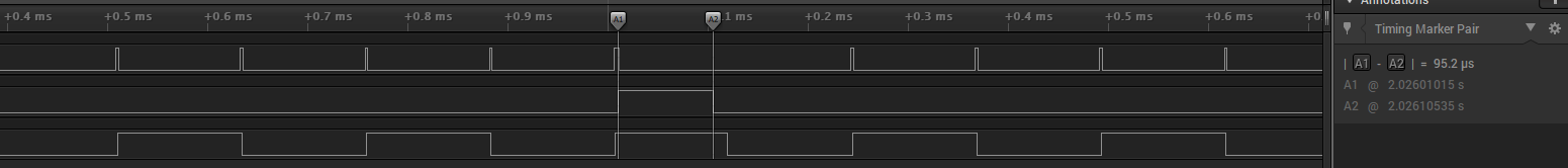
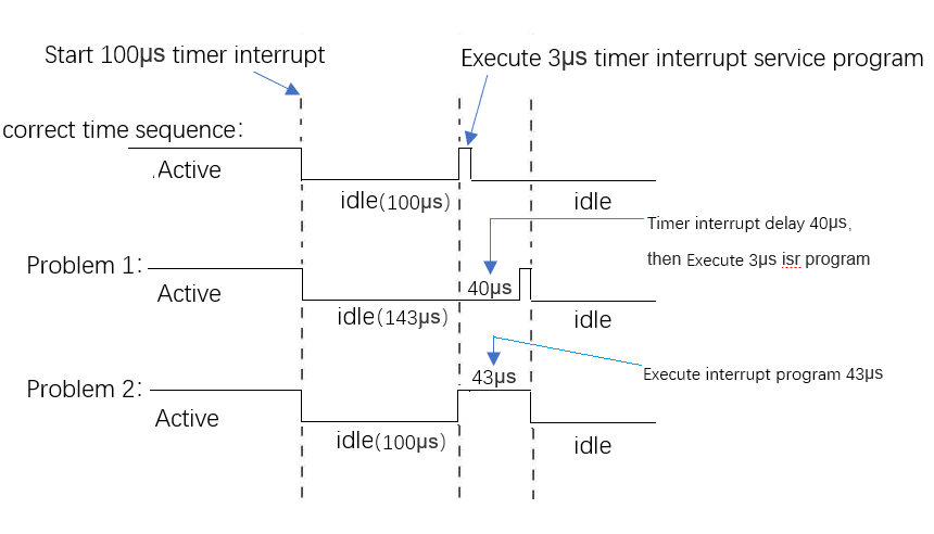
The correct timing sequence is
Line1: LED_INTA
Line2: LED_INTB (when starting TIMRB ,set high ,and when entering interrupt TIMERB , becomes low)
Line3: LED_EXT (when seting PWM , LED_EXT switch)
But
the first time after powering on ,the timing sequence is
there are 40us delay before start TIMERB (what does it do) ,and TIMERB enters interrupt later. So the time of setting PWM is not correct
What's matter?
Another, cfg file is used the example of CC1310 launchpad. rfExamples.cfg, no change