This thread has been locked.

If you have a related question, please click the "Ask a related question" button in the top right corner. The newly created question will be automatically linked to this question.

CCS/CC1310: Does ccfg.c level optimization change settings?

Part Number: CC1310

Tool/software: Code Composer Studio

Hello,

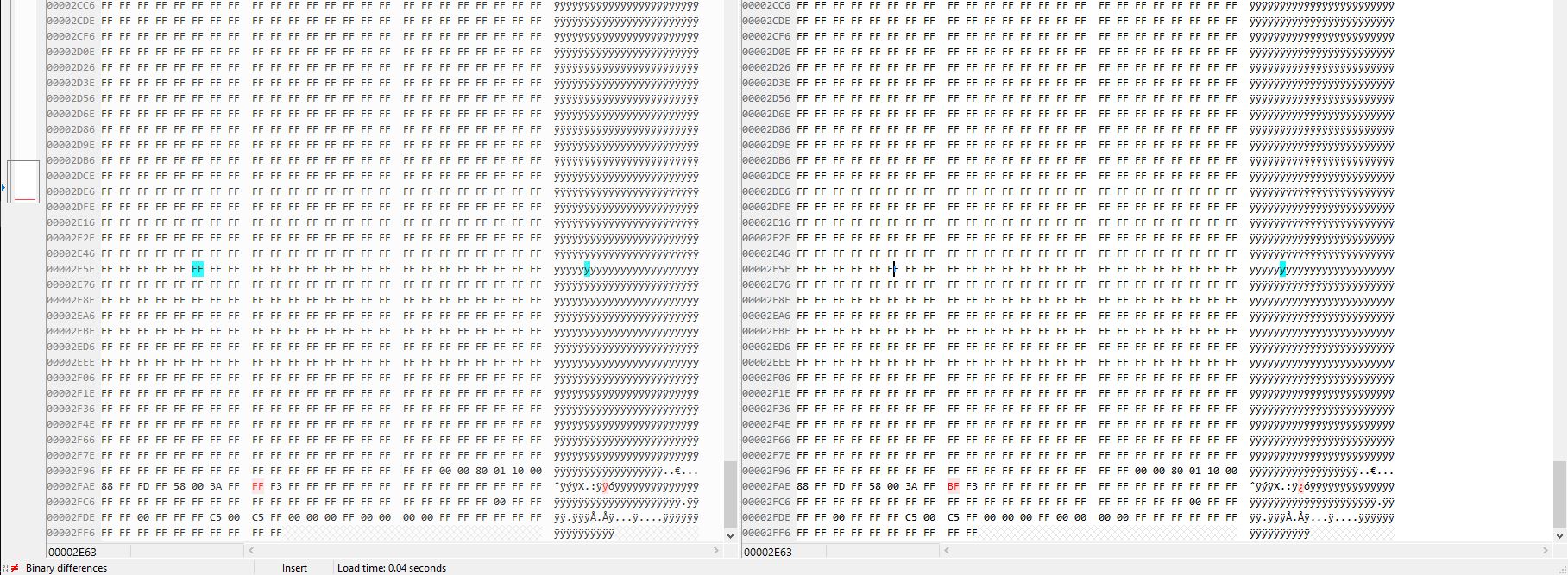
We had a strange problem with the power consumption with one of our low power devices. When we make OTA from older version to newer, the sleep current raised to 2mA, but when we burn the new version directly from CCS, the sleep current is what it should be – 2uA. After looking into the problem it turned out to be that the ccfg was different when burned from CCS.

This is the flash layout of our device:

Bootloader

Bank 1

Bank 2

NVS

ccfg


We’ve noticed that different optimization levels produce different ccfg. This is a problem for us, since we only update the banks.

Is there a way to make ccfg part of the application (bank 1 and bank 2), so that when we make OTA it will be updated as well?

Is there a way to guarantee that ccfg will remain unchanged?


Thank you.

  • Hi Georgi,

    That sounds really strange, CCFG should not be altered by optimization. What fields did change?

    I would highly recommend not updating CCFG after a product is released. The flash page containing CCFG should be locked to prevent any accidental changes to this area.

    Regards,
    Fredrik
  • Hello,

    I attach you a compared picture of ccfg file. The left side is ccfg which our device consuming 1uA and the right side is ccfg which consuming 1.8mA. The only difference is one byte (0xFF <==> 0xBF). Can you tell us what this byte do?

    P.S.: At this moment we are not shure what should change our ccfg file. To be more clear we separate ccfg settings like a .bin file which file we merge with new firmware. By theory nothing and never should be change this file, but some how now we face the one byte difference. Now I did test with different level optimization, and I can`t reproduce difference in ccfg (I`m confuse).

    Thanks!

  • Hi Georgi,

    The bit you are looking at is for selecting 32 kHz clock source. 0xFF = LF RCOSC and 0xBF = LF XOSC. This is something that has to be set by you somehow.

    It looks like you do not have a 32k crystal on your board, right? If so, when the CCFG is set to run off the crystal and it is not present it will run the SCLK_LF from RCOSC_HF instead. This will again prevent the device from entering Standby which explains the current consumption you see.

    Regards,
    Fredrik