Hi
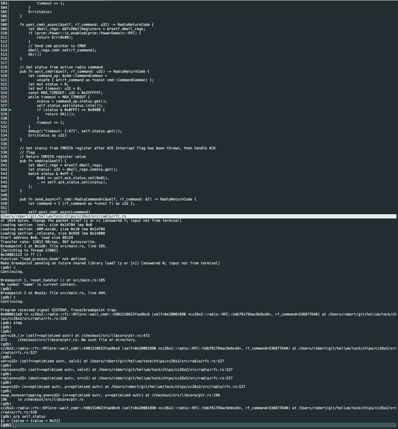
I am trying to use the long range patch with the settings provided below but during the PROP_CMD_TX operation the radio continuously hangs on active (the CMD Status field). I am certain the radio is not actively transmitting and I believe there may be other peripherals the radio is attempting to access as part of this process but I am having trouble finding detailed documentation on this particular patch. If so, I may not have enabled these peripherals or brought them up in my own OS implementation yet and need to start that immediately. Does anyone know if there is some detailed explanation for this operation on the cc13x2 series chips, and if not, can you explain what the radio operation is utilizing to accomplish this operation given these parameters?
Thanks
//*********************************************************************************
// Generated by SmartRF Studio version 2.10.0 (build#110)
// The applied template is compatible with CC13x2 SDK 2.20.xx.xx
// Device: CC1312R Rev. 1.1 (Rev. C)
//
//*********************************************************************************


//*********************************************************************************
// Parameter summary
// Address: 0
// Address0: 0xAA
// Address1: 0xBB
// Frequency: 915.00000 MHz
// Data Format: Serial mode disable
// Deviation: 2.500 kHz
// pktLen: 30
// 802.15.4g Mode: 0
// Select bit order to transmit PSDU octets:: 1
// Packet Length Config: Variable
// Max Packet Length: 128
// Packet Length: 20
// Packet Data: 255
// RX Filter BW: 34.1 kHz
// Symbol Rate: 10.00061 kBaud
// Sync Word Length: 32 Bits
// TX Power: 14 dBm (requires define CCFG_FORCE_VDDR_HH = 1 in ccfg.c, see CC13xx/CC26xx Technical Reference Manual)
// Whitening: No whitening

#include <ti/devices/DeviceFamily.h>
#include DeviceFamily_constructPath(driverlib/rf_mailbox.h)
#include DeviceFamily_constructPath(driverlib/rf_common_cmd.h)
#include DeviceFamily_constructPath(driverlib/rf_prop_cmd.h)
#include <ti/drivers/rf/RF.h>
#include DeviceFamily_constructPath(rf_patches/rf_patch_cpe_prop.h)
#include DeviceFamily_constructPath(rf_patches/rf_patch_rfe_genfsk.h)
#include DeviceFamily_constructPath(rf_patches/rf_patch_mce_sl_longrange.h)
#include "longrange10k2-5k.h"


// TI-RTOS RF Mode Object
RF_Mode RF_prop =
{
    .rfMode = RF_MODE_AUTO,
    .cpePatchFxn = &rf_patch_cpe_prop,
    .mcePatchFxn = &rf_patch_mce_sl_longrange,
    .rfePatchFxn = &rf_patch_rfe_genfsk,
};

// TX Power table
// The RF_TxPowerTable_DEFAULT_PA_ENTRY macro is defined in RF.h and requires the following arguments:
// RF_TxPowerTable_DEFAULT_PA_ENTRY(bias, gain, boost coefficient)
// See the Technical Reference Manual for further details about the "txPower" Command field.
// The PA settings require the CCFG_FORCE_VDDR_HH = 0 unless stated otherwise.
RF_TxPowerTable_Entry txPowerTable[TX_POWER_TABLE_SIZE] =
{
    {-20, RF_TxPowerTable_DEFAULT_PA_ENTRY(0, 3, 0, 2) },
    {-15, RF_TxPowerTable_DEFAULT_PA_ENTRY(1, 3, 0, 2) },
    {-10, RF_TxPowerTable_DEFAULT_PA_ENTRY(2, 3, 0, 4) },
    {-5, RF_TxPowerTable_DEFAULT_PA_ENTRY(4, 3, 0, 5) },
    {0, RF_TxPowerTable_DEFAULT_PA_ENTRY(8, 3, 0, 7) },
    {1, RF_TxPowerTable_DEFAULT_PA_ENTRY(9, 3, 0, 7) },
    {2, RF_TxPowerTable_DEFAULT_PA_ENTRY(10, 3, 0, 9) },
    {3, RF_TxPowerTable_DEFAULT_PA_ENTRY(11, 3, 0, 9) },
    {4, RF_TxPowerTable_DEFAULT_PA_ENTRY(12, 3, 0, 11) },
    {5, RF_TxPowerTable_DEFAULT_PA_ENTRY(14, 3, 0, 12) },
    {6, RF_TxPowerTable_DEFAULT_PA_ENTRY(16, 3, 0, 14) },
    {7, RF_TxPowerTable_DEFAULT_PA_ENTRY(8, 2, 0, 16) },
    {8, RF_TxPowerTable_DEFAULT_PA_ENTRY(22, 3, 0, 32) },
    {9, RF_TxPowerTable_DEFAULT_PA_ENTRY(26, 3, 0, 28) },
    {10, RF_TxPowerTable_DEFAULT_PA_ENTRY(33, 3, 0, 55) },
    {11, RF_TxPowerTable_DEFAULT_PA_ENTRY(23, 2, 0, 42) },
    {12, RF_TxPowerTable_DEFAULT_PA_ENTRY(10, 0, 0, 58) },
    {13, RF_TxPowerTable_DEFAULT_PA_ENTRY(20, 0, 0, 102) }, // The original PA value (12.5 dBm) have been rounded to an integer value.
    {14, RF_TxPowerTable_DEFAULT_PA_ENTRY(63, 0, 1, 79) }, // This setting requires CCFG_FORCE_VDDR_HH = 1.
    RF_TxPowerTable_TERMINATION_ENTRY
};


// Overrides for CMD_PROP_RADIO_DIV_SETUP
uint32_t pOverrides[] =
{
    // override_use_patch_simplelink_long_range.xml
    // PHY: Use MCE RAM patch, RFE RAM patch
    MCE_RFE_OVERRIDE(1,0,0,1,0,0),
    // PHY: Use MCE RAM patch only for Rx (0xE), use MCE ROM bank 6 for Tx (0x6)
    (uint32_t)0x006E88E3,
    // override_synth_prop_863_930_div5.xml
    // Synth: Use 48 MHz crystal as synth clock, enable extra PLL filtering
    (uint32_t)0x02400403,
    // Synth: Set minimum RTRIM to 6
    (uint32_t)0x00068793,
    // Synth: Configure extra PLL filtering
    (uint32_t)0x001C8473,
    // Synth: Configure extra PLL filtering
    (uint32_t)0x00088433,
    // Synth: Set Fref to 4 MHz
    (uint32_t)0x000684A3,
    // Synth: Configure faster calibration
    HW32_ARRAY_OVERRIDE(0x4004,1),
    // Synth: Configure faster calibration
    (uint32_t)0x180C0618,
    // Synth: Configure faster calibration
    (uint32_t)0xC00401A1,
    // Synth: Configure faster calibration
    (uint32_t)0x00010101,
    // Synth: Configure faster calibration
    (uint32_t)0xC0040141,
    // Synth: Configure faster calibration
    (uint32_t)0x00214AD3,
    // Synth: Decrease synth programming time-out by 90 us from default (0x0298 RAT ticks = 166 us)
    (uint32_t)0x02980243,
    // Synth: Set loop bandwidth after lock to 20 kHz
    (uint32_t)0x0A480583,
    // Synth: Set loop bandwidth after lock to 20 kHz
    (uint32_t)0x7AB80603,
    // Synth: Set loop bandwidth after lock to 20 kHz
    (uint32_t)0x00000623,
    // override_phy_simplelink_long_range_dsss4.xml
    // PHY: Configure DSSS SF=4 for payload data
    HW_REG_OVERRIDE(0x5068,0x030C),
    // PHY: Set SimpleLink Long Range bit-inverted sync word pattern (uncoded, before spreading to fixed-size 64-bit pattern): 0x146F
    HW_REG_OVERRIDE(0x5128,0x146F),
    // PHY: Set SimpleLink Long Range sync word pattern (uncoded, before spreading to fixed-size 64-bit pattern): 0xEB90
    HW_REG_OVERRIDE(0x512C,0xEB90),
    // PHY: Reduce demodulator correlator threshold for improved Rx sensitivity
    HW_REG_OVERRIDE(0x5124,0x362E),
    // PHY: Reduce demodulator correlator threshold for improved Rx sensitivity
    HW_REG_OVERRIDE(0x5118,0x004C),
    // PHY: Configure limit on frequency offset compensation tracker
    HW_REG_OVERRIDE(0x5140,0x3E05),
    // override_phy_rx_frontend_simplelink_long_range.xml
    // Rx: Set RSSI offset to adjust reported RSSI by -2 dB (default: 0)
    (uint32_t)0x000288A3,
    // override_phy_rx_aaf_bw_0xd.xml
    // Rx: Set anti-aliasing filter bandwidth to 0xD (in ADI0, set IFAMPCTL3[7:4]=0xD)
    ADI_HALFREG_OVERRIDE(0,61,0xF,0xD),
    // TX power override
    // DC/DC regulator: In Tx with 14 dBm PA setting, use DCDCCTL5[3:0]=0xF (DITHER_EN=1 and IPEAK=7). In Rx, use DCDCCTL5[3:0]=0xC (DITHER_EN=1 and IPEAK=4).
    (uint32_t)0xFFFC08C3,
    // Tx: Set PA trim to max to maximize its output power (in ADI0, set PACTL0=0xF8)
    ADI_REG_OVERRIDE(0,12,0xF8),
    (uint32_t)0xFFFFFFFF,
};


// CMD_PROP_RADIO_DIV_SETUP
// Proprietary Mode Radio Setup Command for All Frequency Bands
rfc_CMD_PROP_RADIO_DIV_SETUP_t RF_cmdPropRadioDivSetup =
{
    .commandNo = 0x3807,
    .status = 0x0000,
    .pNextOp = 0, // INSERT APPLICABLE POINTER: (uint8_t*)&xxx
    .startTime = 0x00000000,
    .startTrigger.triggerType = 0x0,
    .startTrigger.bEnaCmd = 0x0,
    .startTrigger.triggerNo = 0x0,
    .startTrigger.pastTrig = 0x0,
    .condition.rule = 0x1,
    .condition.nSkip = 0x0,
    .modulation.modType = 0x1,
    .modulation.deviation = 0xA,
    .modulation.deviationStepSz = 0x0,
    .symbolRate.preScale = 0xF,
    .symbolRate.rateWord = 0x199A,
    .symbolRate.decimMode = 0x0,
    .rxBw = 0x4C,
    .preamConf.nPreamBytes = 0x2,
    .preamConf.preamMode = 0x0,
    .formatConf.nSwBits = 0x20,
    .formatConf.bBitReversal = 0x0,
    .formatConf.bMsbFirst = 0x0,
    .formatConf.fecMode = 0x8,
    .formatConf.whitenMode = 0x0,
    .config.frontEndMode = 0x0,
    .config.biasMode = 0x1,
    .config.analogCfgMode = 0x0,
    .config.bNoFsPowerUp = 0x0,
    .txPower = 0x9F3F,
    .pRegOverride = pOverrides,
    .centerFreq = 0x0393,
    .intFreq = 0x8000,
    .loDivider = 0x05,
};

// CMD_FS
// Frequency Synthesizer Programming Command
rfc_CMD_FS_t RF_cmdFs =
{
    .commandNo = 0x0803,
    .status = 0x0000,
    .pNextOp = 0, // INSERT APPLICABLE POINTER: (uint8_t*)&xxx
    .startTime = 0x00000000,
    .startTrigger.triggerType = 0x0,
    .startTrigger.bEnaCmd = 0x0,
    .startTrigger.triggerNo = 0x0,
    .startTrigger.pastTrig = 0x0,
    .condition.rule = 0x1,
    .condition.nSkip = 0x0,
    .frequency = 0x0393,
    .fractFreq = 0x0000,
    .synthConf.bTxMode = 0x0,
    .synthConf.refFreq = 0x0,
    .__dummy0 = 0x00,
    .__dummy1 = 0x00,
    .__dummy2 = 0x00,
    .__dummy3 = 0x0000,
};

// CMD_PROP_TX
// Proprietary Mode Transmit Command
rfc_CMD_PROP_TX_t RF_cmdPropTx =
{
    .commandNo = 0x3801,
    .status = 0x0000,
    .pNextOp = 0, // INSERT APPLICABLE POINTER: (uint8_t*)&xxx
    .startTime = 0x00000000,
    .startTrigger.triggerType = 0x0,
    .startTrigger.bEnaCmd = 0x0,
    .startTrigger.triggerNo = 0x0,
    .startTrigger.pastTrig = 0x0,
    .condition.rule = 0x1,
    .condition.nSkip = 0x0,
    .pktConf.bFsOff = 0x0,
    .pktConf.bUseCrc = 0x1,
    .pktConf.bVarLen = 0x1,
    .pktLen = 0x14,
    .syncWord = 0x00000000,
    .pPkt = 0, // INSERT APPLICABLE POINTER: (uint8_t*)&xxx
};

// CMD_PROP_RX
// Proprietary Mode Receive Command
rfc_CMD_PROP_RX_t RF_cmdPropRx =
{
    .commandNo = 0x3802,
    .status = 0x0000,
    .pNextOp = 0, // INSERT APPLICABLE POINTER: (uint8_t*)&xxx
    .startTime = 0x00000000,
    .startTrigger.triggerType = 0x0,
    .startTrigger.bEnaCmd = 0x0,
    .startTrigger.triggerNo = 0x0,
    .startTrigger.pastTrig = 0x0,
    .condition.rule = 0x1,
    .condition.nSkip = 0x0,
    .pktConf.bFsOff = 0x0,
    .pktConf.bRepeatOk = 0x0,
    .pktConf.bRepeatNok = 0x0,
    .pktConf.bUseCrc = 0x1,
    .pktConf.bVarLen = 0x1,
    .pktConf.bChkAddress = 0x0,
    .pktConf.endType = 0x0,
    .pktConf.filterOp = 0x0,
    .rxConf.bAutoFlushIgnored = 0x0,
    .rxConf.bAutoFlushCrcErr = 0x0,
    .rxConf.bIncludeHdr = 0x1,
    .rxConf.bIncludeCrc = 0x0,
    .rxConf.bAppendRssi = 0x0,
    .rxConf.bAppendTimestamp = 0x0,
    .rxConf.bAppendStatus = 0x1,
    .syncWord = 0x00000000,
    .maxPktLen = 0x80,
    .address0 = 0xAA,
    .address1 = 0xBB,
    .endTrigger.triggerType = 0x1,
    .endTrigger.bEnaCmd = 0x0,
    .endTrigger.triggerNo = 0x0,
    .endTrigger.pastTrig = 0x0,
    .endTime = 0x00000000,
    .pQueue = 0, // INSERT APPLICABLE POINTER: (dataQueue_t*)&xxx
    .pOutput = 0, // INSERT APPLICABLE POINTER: (uint8_t*)&xxx
};