This thread has been locked.

If you have a related question, please click the "Ask a related question" button in the top right corner. The newly created question will be automatically linked to this question.

RTOS/CC1312R: ADC Read interval

Part Number: CC1312R

Tool/software: TI-RTOS

We are currently developing CC1312.

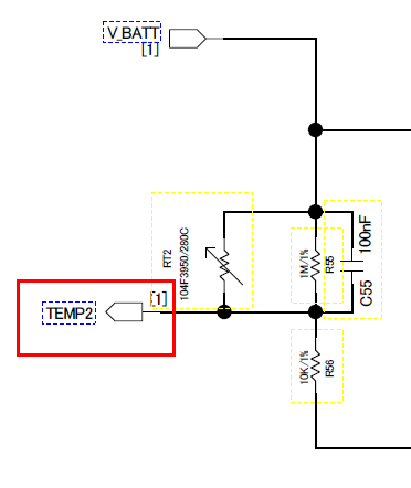
It is in standby mode by default, wake up with a 5 second timer (clock), read the ADC (temperature value).

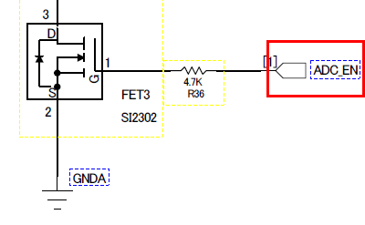
I am having problems reading the ADC.

Every time I wake up with a clock instance, I call ADC_convert

I can not read the correct temperature value.

but when CC1312 wake up and give a delay of 10ms(using Task_Sleep()) , the correct temperature ADC value is read.

I am reading the ADC using the adcsinglechannel example

I have a question.

Is there a delay for reading the ADC correctly after waking up in standby mode?

Where can I find information on this?

  • Your post does not contain enough information to fully answer your question.
    - You write that you read temperature with the ADC. What is the input to the ADC?
    - You write that you are not reading the correct temp value. What do you read when it's incorrect and what do you read when it's correct?
  • answer 1 : The input of the ADC is the value of the temperature sensor as seen in the schematic.
    answer 2 : The current temperature is measured through the electronic thermometer.
    The correct value was the same as the value of the electronic thermometer.
    The incorrect value produces a strange value that is very different from the temperature value.

    <Detail explanation about project>
    1.The circuit configuration consists of [ADC Enable Pin] to reduce current consumption and [ADC Pin] to read Temp sensor.


    2.The operation of the project is basically Standby mode and wake up every 5 seconds through the clock instance.
    3.Detailed operation is as follows.
    (1).Call temp sensor event from clock callback function.
         (Event_post(nodeEventHandle, NODE_EVENT_CHECK_SENSOR);)
    (2).Set [ADC enable Pin] to HIGH.
          (PIN_setOutputValue(pinEnableHandle, ENABLE_ADC, HIGH))
    (3).Delays 10ms
          (Task_sleep(TIME_MS(10));)
    (4).Use ADC_Convert to read the ADC value of the temperature sensor.
         (res1 = ADC_convert(adcTemp1Handle, &adcValue);)


    To reduce current consumption, I remove Task_sleep(TIME_MS(10)).
    However, when reading the ADC value, the correct temperature value could not be read.

    1.Do I need a delay to read the correct ADC? ( Is there an ADC document about delay? (about correct adc read))

    2.If I do not have problems with software, do I need to modify it circuit?

    Thanks.

  • Have you measured the voltage on the temp2 node using a scope? Since you use a 100 nF cap I assume this node needs some time to reach a valid state after you switch this path in.
  • I removed 100 nF Cap and the normal ADC value is read. Thanks.