This thread has been locked.

If you have a related question, please click the "Ask a related question" button in the top right corner. The newly created question will be automatically linked to this question.

CC1312R: Contiki-NG : adding UART1 function

Part Number: CC1312R


Hi

My customer is trying to add UART1 feature in Contiki-NG.
He modified codes based on UART0 which is already implemented.
The HW is CC1312R1_LAUNCHXL.

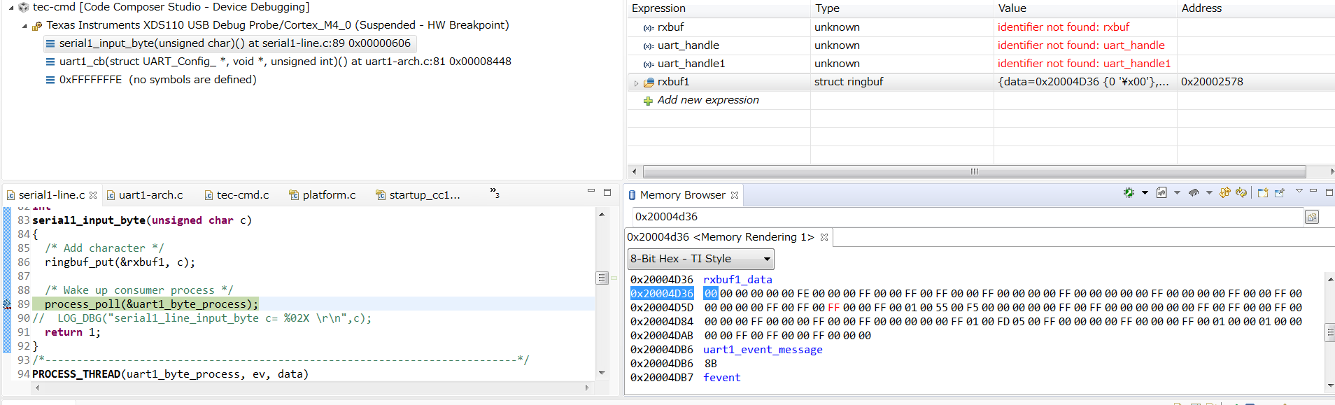
Even nothing is connected to UART1 RX pin (DIO_12 is assigned), some data are received in RX buffer.


The below codes were added/modified. Are there any missing configurations?
contiki-ng\arch\platform\simplelink\cc13xx-cc26xx\launchpad\cc1312r1\CC1312R1_LAUNCHXL.c / CC1312R1_LAUNCHXL.h

/*

*  =============================== UART ===============================

*/

#include <ti/drivers/UART.h>

#include <ti/drivers/uart/UARTCC26XX.h>


#if TI_UART_CONF_ENABLE


UARTCC26XX_Object uartCC26XXObjects[CC1312R1_LAUNCHXL_UARTCOUNT];


uint8_t uartCC26XXRingBuffer[CC1312R1_LAUNCHXL_UARTCOUNT][32];


const UARTCC26XX_HWAttrsV2 uartCC26XXHWAttrs[CC1312R1_LAUNCHXL_UARTCOUNT] = {

#if TI_UART_CONF_UART0_ENABLE

    {

        .baseAddr       = UART0_BASE,

        .powerMngrId    = PowerCC26XX_PERIPH_UART0,

        .intNum         = INT_UART0_COMB,

        .intPriority    = ~0,

        .swiPriority    = 0,

        .txPin          = CC1312R1_LAUNCHXL_UART_TX,

        .rxPin          = CC1312R1_LAUNCHXL_UART_RX,

        .ctsPin         = PIN_UNASSIGNED,

        .rtsPin         = PIN_UNASSIGNED,

        .ringBufPtr     = uartCC26XXRingBuffer[CC1312R1_LAUNCHXL_UART0],

        .ringBufSize    = sizeof(uartCC26XXRingBuffer[CC1312R1_LAUNCHXL_UART0]),

        .txIntFifoThr   = UARTCC26XX_FIFO_THRESHOLD_1_8,

        .rxIntFifoThr   = UARTCC26XX_FIFO_THRESHOLD_4_8,

        .errorFxn       = NULL

    },

#endif

/* UART1 -181101(I) ↓↓↓  - */

#if TI_UART_CONF_UART1_ENABLE

    {

        .baseAddr       = UART1_BASE,

        .powerMngrId    = PowerCC26X2_PERIPH_UART1,

        .intNum         = INT_UART1_COMB,

        .intPriority    = ~0,

        .swiPriority    = 0,

        .txPin          = CC1312R1_LAUNCHXL_UART1_TX,

        .rxPin          = CC1312R1_LAUNCHXL_UART1_RX,

        .ctsPin         = CC1312R1_LAUNCHXL_UART1_CTS,

        .rtsPin         = CC1312R1_LAUNCHXL_UART1_RTS,

        .ringBufPtr     = uartCC26XXRingBuffer[CC1312R1_LAUNCHXL_UART1],

        .ringBufSize    = sizeof(uartCC26XXRingBuffer[CC1312R1_LAUNCHXL_UART1]),

        .txIntFifoThr   = UARTCC26XX_FIFO_THRESHOLD_1_8,

        .rxIntFifoThr   = UARTCC26XX_FIFO_THRESHOLD_4_8,

        .errorFxn       = NULL

    }

#endif

/* -181101(I) ↑↑↑  - */

};


const UART_Config UART_config[CC1312R1_LAUNCHXL_UARTCOUNT] = {

#if TI_UART_CONF_UART0_ENABLE

    {

        .fxnTablePtr = &UARTCC26XX_fxnTable,

        .object      = &uartCC26XXObjects[CC1312R1_LAUNCHXL_UART0],

        .hwAttrs     = &uartCC26XXHWAttrs[CC1312R1_LAUNCHXL_UART0]

    },

#endif

/* UART1 -181101(I) ↓↓↓  - */

#if TI_UART_CONF_UART1_ENABLE

    {

        .fxnTablePtr = &UARTCC26XX_fxnTable,

        .object      = &uartCC26XXObjects[CC1312R1_LAUNCHXL_UART1],

        .hwAttrs     = &uartCC26XXHWAttrs[CC1312R1_LAUNCHXL_UART1]

    }

#endif

/* -181101(I) ↑↑↑  - */

};

typedef enum CC1312R1_LAUNCHXL_UARTName {

#if TI_UART_CONF_UART0_ENABLE

    CC1312R1_LAUNCHXL_UART0 = 0,

#endif

#if TI_UART_CONF_UART1_ENABLE

    CC1312R1_LAUNCHXL_UART1,                      /* -181101(I)- */

#endif


    CC1312R1_LAUNCHXL_UARTCOUNT

} CC1312R1_LAUNCHXL_UARTName;


const PIN_Config BoardGpioInitTable[] = {


    CC1312R1_LAUNCHXL_PIN_RLED | PIN_GPIO_OUTPUT_EN | PIN_GPIO_LOW | PIN_PUSHPULL | PIN_DRVSTR_MAX,       /* LED initially off          */

    CC1312R1_LAUNCHXL_PIN_GLED | PIN_GPIO_OUTPUT_EN | PIN_GPIO_LOW | PIN_PUSHPULL | PIN_DRVSTR_MAX,       /* LED initially off          */

    CC1312R1_LAUNCHXL_PIN_BTN1 | PIN_INPUT_EN | PIN_PULLUP | PIN_IRQ_BOTHEDGES | PIN_HYSTERESIS,          /* Button is active low       */

    CC1312R1_LAUNCHXL_PIN_BTN2 | PIN_INPUT_EN | PIN_PULLUP | PIN_IRQ_BOTHEDGES | PIN_HYSTERESIS,          /* Button is active low       */

    CC1312R1_LAUNCHXL_SPI_FLASH_CS | PIN_GPIO_OUTPUT_EN | PIN_GPIO_HIGH | PIN_PUSHPULL | PIN_DRVSTR_MIN,  /* External flash chip select */

    CC1312R1_LAUNCHXL_UART_RX   | PIN_INPUT_EN | PIN_PULLDOWN,                                            /* UART0 RX via debugger back channel */

    CC1312R1_LAUNCHXL_UART_TX   | PIN_GPIO_OUTPUT_EN | PIN_GPIO_HIGH | PIN_PUSHPULL,                      /* UART0 TX via debugger back channel */

    CC1312R1_LAUNCHXL_UART1_RX  | PIN_INPUT_EN | PIN_PULLDOWN,                                            /* IOID_12 UART1 RX -181101(I)- */

    CC1312R1_LAUNCHXL_UART1_TX  | PIN_GPIO_OUTPUT_EN | PIN_GPIO_LOW  | PIN_PULLDOWN,                      /* IOID_15 UART1 TX -181101(I)- */

    CC1312R1_LAUNCHXL_UART1_CTS | PIN_INPUT_EN | PIN_PULLDOWN,                                            /* IOID_21 UART1 CTS -181101(I)- */

    CC1312R1_LAUNCHXL_UART1_RTS | PIN_GPIO_OUTPUT_EN | PIN_GPIO_LOW  | PIN_PULLDOWN,                      /* IOID_22 UART1 RTS -181101(I)- */

    CC1312R1_LAUNCHXL_SPI0_MOSI | PIN_INPUT_EN | PIN_PULLDOWN,                                            /* SPI master out - slave in */

    CC1312R1_LAUNCHXL_SPI0_MISO | PIN_INPUT_EN | PIN_PULLDOWN,                                            /* SPI master in - slave out */

    CC1312R1_LAUNCHXL_SPI0_CLK | PIN_INPUT_EN | PIN_PULLDOWN,                                             /* SPI clock */


    PIN_TERMINATE

};


/* Digital IOs */

#define CC1312R1_LAUNCHXL_DIO0                  IOID_0

#define CC1312R1_LAUNCHXL_DIO1                  IOID_1

#define CC1312R1_LAUNCHXL_DIO12                 PIN_UNASSIGNED  /* UART1_RX -181101(D)- */

#define CC1312R1_LAUNCHXL_DIO15                 PIN_UNASSIGNED  /* UART1_TX -181101(D)- */

#define CC1312R1_LAUNCHXL_DIO16_TDO             IOID_16

#define CC1312R1_LAUNCHXL_DIO17_TDI             IOID_17

#define CC1312R1_LAUNCHXL_DIO21                 PIN_UNASSIGNED  /* UART1_CTS -181101(D)- */

#define CC1312R1_LAUNCHXL_DIO22                 PIN_UNASSIGNED  /* UART1_RTS -181101(D)- */

/* UART Board */

#define CC1312R1_LAUNCHXL_UART0_RX              IOID_2          /* RXD */

#define CC1312R1_LAUNCHXL_UART0_TX              IOID_3          /* TXD */

#define CC1312R1_LAUNCHXL_UART0_CTS             IOID_19         /* CTS */

#define CC1312R1_LAUNCHXL_UART0_RTS             IOID_18         /* RTS */

#define CC1312R1_LAUNCHXL_UART1_RX              IOID_12         /* RXD -181101(I)- */

#define CC1312R1_LAUNCHXL_UART1_TX              IOID_15         /* TXD -181101(I)- */

#define CC1312R1_LAUNCHXL_UART1_CTS             IOID_21         /* CTS -181101(I)- */

#define CC1312R1_LAUNCHXL_UART1_RTS             IOID_22         /* RTS -181101(I)- */

/* For backward compatibility */

#define CC1312R1_LAUNCHXL_UART_RX               CC1312R1_LAUNCHXL_UART0_RX

#define CC1312R1_LAUNCHXL_UART_TX               CC1312R1_LAUNCHXL_UART0_TX

#define CC1312R1_LAUNCHXL_UART_CTS              CC1312R1_LAUNCHXL_UART0_CTS

#define CC1312R1_LAUNCHXL_UART_RTS              CC1312R1_LAUNCHXL_UART0_RTS


Thanks and regards,
KoT

  • Hi KoT,

    I'm having trouble understanding what is modified here. It should not be necessary modifying the CC1312R1_LAUNCHXL.c file. Simply assigning the CC1312R1_LAUNCHXL_UART1_RX and CC1312R1_LAUNCHXL_UART1_TX pins in the CC1312R1_LAUNCHXL.h should be sufficient.

    However, are you planning on using UART1 via the UART driver directly, or through similar means as uart0-arch?
  • Hi Edvard,

    >It should not be necessary modifying the CC1312R1_LAUNCHXL.c file.

    Do you mean no changes are required in CC1312R1_LAUNCHXL.c ?
    I thought below configurations are done inside CC1312R1_LAUNCHXL.c, so they are needed, no?
    - BoardGpioInitTable[]
    - uartCC26XXHWAttrs
    - UART_Config

    >However, are you planning on using UART1 via the UART driver directly, or through similar means as uart0-arch?

    Customer wants to use UART1 with similar means as UART0, so they mimic UART0 implementation codes for UART1 as well.
    UART0 is used as log output for debug.
    UART1 is used for custom command with binary mode.

    Thanks and regards,
    KoT

  • You need to configure the following:
    * In CC1312R1_LAUNCHXL.h, you need to assign both CC1312R1_LAUNCHXL_UART1_RX and CC1312R1_LAUNCHXL_UART1_TX to the pins you are going to use. Optionally, the CC1312R1_LAUNCHXL_UART1_CTS and CC1312R1_LAUNCHXL_UART1_RTS pins must be used if you are using flow control.
    * In your project-config.h, you need to set the following define TI_UART_CONF_UART1_ENABLE to 1. The define TI_UART_CONF_ENABLE must also be set to 1, however, it defaults to 1 if not overriden.

    Now you can use the Board_UART1 peripheral defined in Board.h. It should probably be enough to copy and paste the uart0-arch.h/c toa uart1-arch.h/c, and replace the peripheral with Board_UART1.

  • This thread might help, too.

    https://e2e.ti.com/support/wireless-connectivity/sub-1-ghz/f/156/t/734222

  • Hi Edvard, Keith,

    Thanks for your inputs, but customer cannot use UART1, yet.
    We are checking any missing implementation you pointed out and let you know results soon.

    Thanks and regards,
    KoT

  • Hi Edvard, Keith,

    Customer did below modifications in their codes, but UART1 does not work.
    It seems initialization fails. Just after UART1 initialization, RSR bits are already set as below.
    (these bits are 0 for UART0)


    In CC1312R1_LAUNCHXL.h, UART1 pins are assigned:
    #define CC1312R1_LAUNCHXL_UART0_RX              IOID_2          /* RXD */
    #define CC1312R1_LAUNCHXL_UART0_TX              IOID_3          /* TXD */
    #define CC1312R1_LAUNCHXL_UART0_CTS             IOID_19         /* CTS */
    #define CC1312R1_LAUNCHXL_UART0_RTS             IOID_18         /* RTS */
    #define CC1312R1_LAUNCHXL_UART1_RX              IOID_12         /* RXD -181101(I)- */
    #define CC1312R1_LAUNCHXL_UART1_TX              IOID_15         /* TXD -181101(I)- */
    #define CC1312R1_LAUNCHXL_UART1_CTS             IOID_21         /* CTS -181101(I)- */
    #define CC1312R1_LAUNCHXL_UART1_RTS             IOID_22         /* RTS -181101(I)- */

    In CC1312R1_LAUNCHXL.c, PIN_Config BoardGpioInitTable[] is changed:
    const PIN_Config BoardGpioInitTable[] = {
          :
       CC1312R1_LAUNCHXL_UART_RX   | PIN_INPUT_EN | PIN_PULLDOWN,                                           /* UART0 RX via debugger back channel */
       CC1312R1_LAUNCHXL_UART_TX   | PIN_GPIO_OUTPUT_EN | PIN_GPIO_HIGH | PIN_PUSHPULL,   /* UART0 TX via debugger back channel */
       CC1312R1_LAUNCHXL_UART1_RX | PIN_INPUT_EN | PIN_PULLDOWN,                                            /* IOID_12 UART1 RX -181101(I)- */
       CC1312R1_LAUNCHXL_UART1_TX | PIN_GPIO_OUTPUT_EN | PIN_GPIO_HIGH | PIN_PUSHPULL, /* IOID_15 UART1 TX -181101(I)- */
       CC1312R1_LAUNCHXL_UART1_CTS | PIN_INPUT_EN | PIN_PULLDOWN,                                            /* IOID_21 UART1 CTS -181101(I)- */
       CC1312R1_LAUNCHXL_UART1_RTS | PIN_GPIO_OUTPUT_EN | PIN_GPIO_HIGH | PIN_PUSHPULL, /* IOID_22 UART1 RTS -181101(I)- */

       PIN_TERMINATE
    };


    uartCC26XX_HWAttrsV2 is modified to add UART1:
    const UARTCC26XX_HWAttrsV2 uartCC26XXHWAttrs[CC1312R1_LAUNCHXL_UARTCOUNT] = {
    #if TI_UART_CONF_UART0_ENABLE
       {
           .baseAddr       = UART0_BASE,
           .powerMngrId   = PowerCC26XX_PERIPH_UART0,
           .intNum         = INT_UART0_COMB,
           .intPriority   = ~0,
           .swiPriority   = 0,
           .txPin         = CC1312R1_LAUNCHXL_UART_TX,
           .rxPin         = CC1312R1_LAUNCHXL_UART_RX,
           .ctsPin         = PIN_UNASSIGNED,
           .rtsPin         = PIN_UNASSIGNED,
           .ringBufPtr     = uartCC26XXRingBuffer[CC1312R1_LAUNCHXL_UART0],
           .ringBufSize   = sizeof(uartCC26XXRingBuffer[CC1312R1_LAUNCHXL_UART0]),
           .txIntFifoThr   = UARTCC26XX_FIFO_THRESHOLD_1_8,
           .rxIntFifoThr   = UARTCC26XX_FIFO_THRESHOLD_4_8,
           .errorFxn       = NULL
       },
    #endif
    /* UART1 -181101(I) ↓↓↓ - */
    #if TI_UART_CONF_UART1_ENABLE
       {
           .baseAddr       = UART1_BASE,
           .powerMngrId   = PowerCC26X2_PERIPH_UART1,
           .intNum         = INT_UART1_COMB,
           .intPriority   = ~0,
           .swiPriority   = 0,
           .txPin         = CC1312R1_LAUNCHXL_UART1_TX,
           .rxPin         = CC1312R1_LAUNCHXL_UART1_RX,
           .ctsPin         = CC1312R1_LAUNCHXL_UART1_CTS,
           .rtsPin         = CC1312R1_LAUNCHXL_UART1_RTS,
           .ringBufPtr     = uartCC26XXRingBuffer[CC1312R1_LAUNCHXL_UART1],
           .ringBufSize   = sizeof(uartCC26XXRingBuffer[CC1312R1_LAUNCHXL_UART1]),
           .txIntFifoThr   = UARTCC26XX_FIFO_THRESHOLD_1_8,
           .rxIntFifoThr   = UARTCC26XX_FIFO_THRESHOLD_4_8,
           .errorFxn       = NULL
       }
    #endif
    /* -181101(I) ↑↑↑ - */
    };

    UART_Config is modified:
    const UART_Config UART_config[CC1312R1_LAUNCHXL_UARTCOUNT] = {
    #if TI_UART_CONF_UART0_ENABLE
       {
           .fxnTablePtr = &UARTCC26XX_fxnTable,
           .object     = &uartCC26XXObjects[CC1312R1_LAUNCHXL_UART0],
           .hwAttrs     = &uartCC26XXHWAttrs[CC1312R1_LAUNCHXL_UART0]
       },
    #endif
    /* UART1 -181101(I) ↓↓↓ - */
    #if TI_UART_CONF_UART1_ENABLE
       {
           .fxnTablePtr = &UARTCC26XX_fxnTable,
           .object     = &uartCC26XXObjects[CC1312R1_LAUNCHXL_UART1],
           .hwAttrs     = &uartCC26XXHWAttrs[CC1312R1_LAUNCHXL_UART1]
       }
    #endif
    /* -181101(I) ↑↑↑ - */
    };

    Below enum is also modified:
    typedef enum CC1312R1_LAUNCHXL_UARTName {
    #if TI_UART_CONF_UART0_ENABLE
       CC1312R1_LAUNCHXL_UART0 = 0,
    #endif
    #if TI_UART_CONF_UART1_ENABLE
       CC1312R1_LAUNCHXL_UART1,                     /* -181101(I)- */
    #endif

       CC1312R1_LAUNCHXL_UARTCOUNT
    } CC1312R1_LAUNCHXL_UARTName;


    TI_UART_CONF_UART1_ENABLE is defined to 1.
    PowerCC26X2.h/c are used.

    Any points to be checked?

    Thanks and regards,
    KoT

  • Hi Edvard, Keith,

    We found the issue in pin configuration. UART1_RX pin is active-Low signal, so it needs to be pull-down for proper operation.
    The pull setting is copy&paste from UART0 setting.

    const PIN_Config BoardGpioInitTable[] = {
          :
       CC1312R1_LAUNCHXL_UART_RX   | PIN_INPUT_EN | PIN_PULLDOWN,                                           /* UART0 RX via debugger back channel */
       CC1312R1_LAUNCHXL_UART_TX   | PIN_GPIO_OUTPUT_EN | PIN_GPIO_HIGH | PIN_PUSHPULL,   /* UART0 TX via debugger back channel */
       CC1312R1_LAUNCHXL_UART1_RX | PIN_INPUT_EN | PIN_PULLDOWN,                                            /* IOID_12 UART1 RX -181101(I)- */

    On the Launchpad, UART0_RX is connected to TM4C and I guess TM4C drives UART0_RX to high as long as no active pulses on UART receive line. So no issue was observed on UART0.
    I think UART0 code also needs to be updated to PULLUP to avoid confusion.

    Thanks and regards,
    KoT

  • Of course, I forgot about the default initialization in BoardGpioInitTable... Yes, the UART0 pins are default initialized in the BoardGpioInitTable for convenience. This means that when you want to use UART1 with some other pins you need to either add the pins to the BoardGpioInitTable (as you have outlined above), or manually initialize them in your uart1-arch module.
  • I had one mistake in previous post.

    Wrong:
    UART1_RX pin is active-Low signal, so it needs to be pull-down for proper operation.

    Correct:
    UART1_RX pin is active-Low signal, so it needs to be pull-up for proper operation.

    So current pin configuration for UART0_RX is not correct, even there is no issue on Launchpad hardware.

    Thanks and regards,
    KoT

  • So just to confirm, with the pull-up configuration the UART1 line now works?
  • Yes. UART1_RX with internal pull-up works fine.

    Thanks and regards,
    KoT

  • Ok, thanks for the feedback KoT. I will create a PR for this.