This thread has been locked.

If you have a related question, please click the "Ask a related question" button in the top right corner. The newly created question will be automatically linked to this question.

CCS/CC1310: SPI communication between CC1310 (master) and AFE4300 (slave)

Part Number: CC1310
Other Parts Discussed in Thread: AFE4300

Tool/software: Code Composer Studio

Hello,

I'm trying to make SPI communication work between CC1310 (as master) and an AFE4300 sensor (as slave). I'm using the CC1310 Launchpad and CCS 8.2.0.

My current code is (inside a thread, building on the empty project from the Resource Explorer):

    GPIO_init();
    SPI_init();

    SPI_Handle      spiHandle;
    SPI_Params      spiParams;
    SPI_Transaction transaction;

    uint8_t txBuf[3];
    uint8_t rxBuf[3];

    txBuf[0]=0b00100011;
    txBuf[1]=0b00000000;
    txBuf[2]=0b00000000;

    uint8_t         transmission[3];
    bool            transferOK = false;
    SPI_Status      transactionStatus;
    uint8_t         receiveBuf[3];

    /* RESET PROCEDURE FOR AFE4300 */

    usleep(100000);
    GPIO_write(Board_GPIO_AFE_RST,0);
    usleep(100000);
    GPIO_write(Board_GPIO_AFE_RST,1);
    usleep(100000);

     /* SPE pin of AFE4300 is permanently pulled down because we have only one master-slave SPI connection. We don't need to pull the SPE pin down in order to communicate. */

     /* INITIALIZATION OF SPI PARAMS */

     SPI_Params_init(&spiParams);
     spiParams.frameFormat = SPI_POL0_PHA1;                 // AFE4300 uses POL0_PHA1 as mode: idle state of SCLK is LOW, Data is changed on rising edge and sampled on falling edge
     spiParams.mode = SPI_MASTER;                           // CC1310 is transmitting as master
     spiParams.transferMode = SPI_MODE_BLOCKING;            // blocking mode: we only use one thread, so callback function would only cause unnecessary overhead
     spiParams.bitRate = 4000000;                           // supported bit rate by AFE4300: <= 4MHz
     spiParams.dataSize = 8;

     spiHandle = SPI_open(Board_SPI1, &spiParams);

     transaction.count = 3;
     transaction.txBuf = (void *) txBuf;
     transaction.rxBuf = (void *) rxBuf;

     transferOK = SPI_transfer(spiHandle, &transaction);

     transactionStatus = transaction.status;

     SPI_close(spiHandle);

Now this isn't working. When I run the program, it sets transferOK as true and transactionStatus as TRANSFER_COMPLETED, but the results in rxBuf are rubbish. Looking at the SPI lines, I see something like this:
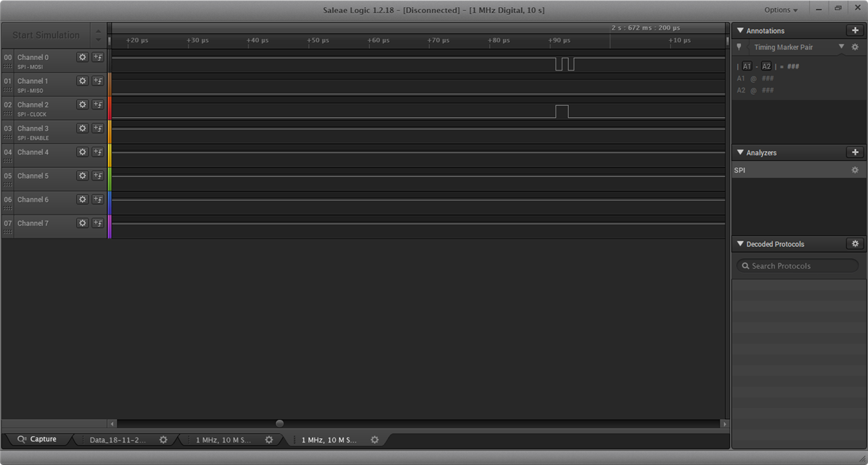

Obviously, there's no real clock signal and the MOSI signal doesn't make sense either.

Weirdly, when I take a far too huge value for transaction.count, it suddenly produces something looking like a clock signal, though the width is off and the MOSI signal doesn't make sense at all either:


First I was using Board_SPI0, but after taking a deeper look into the Board.h files etc. I though it might cause problems because it's used for flashing. Also, the AFE4300 wants the CLK line to be low when idle and the CLK pin of SPI0 is configured to be high at default, so it stays high except when calling SPI_transfer(), which I thought might be causing problems. I then switched to Board_SPI1, by making the following changes to the code:

    - in CC1310_LAUNCHXL.h, I changed the pins to:
        #define CC1310_LAUNCHXL_SPI1_MISO             IOID_15         /* SPI for AFE */
        #define CC1310_LAUNCHXL_SPI1_MOSI             IOID_22
        #define CC1310_LAUNCHXL_SPI1_CLK              IOID_21
      those pins are currently not connected to the AFE4300, but that shouldn't alter the signals that can be measured via Logic Analyzer.
    - in CC1310_LAUNCHXL.c, I added the following lines to PIN-Config BoardGpioInitTable[] right before PIN_TERMINATE:
        CC1310_LAUNCHXL_SPI1_MOSI | PIN_GPIO_OUTPUT_EN | PIN_GPIO_LOW | PIN_PUSHPULL | PIN_INPUT_DIS | PIN_DRVSTR_MED,                                      /* SPI master out - slave in */
        CC1310_LAUNCHXL_SPI1_MISO | PIN_INPUT_EN | PIN_PULLDOWN,                                      /* SPI master in - slave out */
        CC1310_LAUNCHXL_SPI1_CLK  | PIN_GPIO_OUTPUT_EN | PIN_GPIO_LOW | PIN_PUSHPULL | PIN_INPUT_DIS | PIN_DRVSTR_MED,                                      /* SPI clock */

That didn't help though.

Right now I'm out of ideas how I might be using the SPI module wrong. Could you please help me?

Best regards, Alissa

  • Normally SPI communication need to set the CSn line.

    This can, as an example, be done as:

    PIN_Config CSnPinTable[] =
    {
    
       CC1310_LAUNCHXL_DIO11 | PIN_GPIO_OUTPUT_EN | PIN_GPIO_HIGH | PIN_PUSHPULL | PIN_DRVSTR_MIN,         /* Used as CSn */
       PIN_TERMINATE
    };

        PIN_State   CSnState;
        PIN_Handle  CSnPin;

        CSnPin = PIN_open(&CSnState, CSnPinTable);

    The frame format could be set with:


    spiParams.frameFormat = SPI_POL0_PHA0;

    More details could be found by reading the driver documentation: dev.ti.com/.../_s_p_i_8h.html

    and the Synchronous Serial Interface (SSI) section in www.ti.com/.../swcu117h.pdf

  • Hello,

    thanks for your answer and suggestions.

    I haven't used the CS pin so far because (as commented in my code) the SPI enable pin of the AFE is pinned low without connection to the CC1310. I thought this would mean using CS in the software is unnecessary because it has no physical effect on the SPI protocol.
    I don't understand your suggestion here completely - where do you suppose I open this pin? Inside of my thread so I can manually set the CS pin to 0 before each SPI_transfer()?

    As to the frame format: you can see in my code snippet that I've already set spiParams.frameFormat = SPI_POL0_PHA1. This seems to correspond to the AFE4300 data sheet and has also been recommended at some other place in the e2e forum for AFE SPI communication. Is this wrong?

    Best regards
    Alissa
  • Disregard my last answer, I see now that the AFE4300 does not need a CSn signal. I have to look at this in more detail tomorrow.
  • I did a test similar to yours. I have used the SPI_master example as a starting point. Below is what I have changed in the code:

    const PIN_Config BoardGpioInitTable[] = {
    
        CC1310_LAUNCHXL_PIN_RLED | PIN_GPIO_OUTPUT_EN | PIN_GPIO_LOW | PIN_PUSHPULL | PIN_DRVSTR_MAX,       /* LED initially off          */
        CC1310_LAUNCHXL_PIN_GLED | PIN_GPIO_OUTPUT_EN | PIN_GPIO_LOW | PIN_PUSHPULL | PIN_DRVSTR_MAX,       /* LED initially off          */
        CC1310_LAUNCHXL_PIN_BTN1 | PIN_INPUT_EN | PIN_PULLUP | PIN_IRQ_BOTHEDGES | PIN_HYSTERESIS,          /* Button is active low       */
        CC1310_LAUNCHXL_PIN_BTN2 | PIN_INPUT_EN | PIN_PULLUP | PIN_IRQ_BOTHEDGES | PIN_HYSTERESIS,          /* Button is active low       */
        CC1310_LAUNCHXL_SPI_FLASH_CS | PIN_GPIO_OUTPUT_EN | PIN_GPIO_HIGH | PIN_PUSHPULL | PIN_DRVSTR_MIN,  /* External flash chip select */
        CC1310_LAUNCHXL_UART_RX | PIN_INPUT_EN | PIN_PULLDOWN,                                              /* UART RX via debugger back channel */
        CC1310_LAUNCHXL_UART_TX | PIN_GPIO_OUTPUT_EN | PIN_GPIO_HIGH | PIN_PUSHPULL,                        /* UART TX via debugger back channel */
        CC1310_LAUNCHXL_SPI0_MOSI | PIN_INPUT_EN | PIN_PULLDOWN,                                            /* SPI master out - slave in */
        CC1310_LAUNCHXL_SPI0_MISO | PIN_INPUT_EN | PIN_PULLDOWN,                                            /* SPI master in - slave out */
        CC1310_LAUNCHXL_SPI0_CLK | PIN_INPUT_EN | PIN_PULLDOWN,                                             /* SPI clock */
        CC1310_LAUNCHXL_SPI1_MOSI | PIN_INPUT_EN | PIN_PULLDOWN,                                            /* SPI master out - slave in */
        CC1310_LAUNCHXL_SPI1_MISO | PIN_INPUT_EN | PIN_PULLDOWN,                                            /* SPI master in - slave out */
        CC1310_LAUNCHXL_SPI1_CLK | PIN_INPUT_EN | PIN_PULLDOWN,                                             /* SPI clock */
    
        CC1310_LAUNCHXL_DIO11 | PIN_GPIO_OUTPUT_EN | PIN_GPIO_HIGH | PIN_PUSHPULL | PIN_DRVSTR_MIN,         /* Used as CSn */
    
        PIN_TERMINATE
    };
    
    
    #define CC1310_LAUNCHXL_SPI1_MISO             IOID_15
    #define CC1310_LAUNCHXL_SPI1_MOSI             IOID_22
    #define CC1310_LAUNCHXL_SPI1_CLK              IOID_21
    #define CC1310_LAUNCHXL_SPI1_CSN              PIN_UNASSIGNED
        /* Open SPI as master (default) */
        SPI_Params_init(&spiParams);
        spiParams.frameFormat = SPI_POL0_PHA1;
    spiParams.bitRate = 4000000; spiParams.dataSize = 8; //masterSpi = SPI_open(CC1310_LAUNCHXL_SPI1, &spiParams); masterSpi = SPI_open(Board_SPI1, &spiParams); if (masterSpi == NULL) { Display_printf(display, 0, 0, "Error initializing master SPI\n"); while (1); } else { Display_printf(display, 0, 0, "Master SPI initialized\n"); } /* Initialize master SPI transaction structure */ //memset((void *) masterRxBuffer, 0, SPI_MSG_LENGTH); transaction.count = 3; transaction.txBuf = (void *) cmdDeviceID_Tx; transaction.rxBuf = (void *) cmdDeviceID_Rx;

    The result looks like this: 

  • Thank you! It seems changing the options of the SPI1 pins in BoardGpioInitTable solved my problem.