This thread has been locked.

If you have a related question, please click the "Ask a related question" button in the top right corner. The newly created question will be automatically linked to this question.

CC1101: Programming CC1101 for 345 MHz ASK

Part Number: CC1101
Other Parts Discussed in Thread: TEST2

I have two CC1101's communicating with GFSK at 434 MHz. They are connected to Raspberry Pi's, and use the GitHub SpaceTeddy library.

Since, the CC1101 board and antenna communicates fine at 434 and 315 MHz, does that mean it is likely to work at 345 MHz?

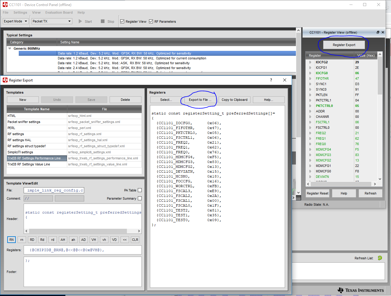
What is required to set 345 MHz ASK? 

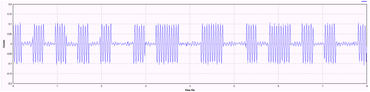
The goal is to read a 64 bit, manchester encoded signal including start bits, and CRC:

  • According to the datasheet, CC1101 supports 345 MHz. See datasheet/ SmartRF Studio on how to set the frequency and modulation format.

    Start bits, does that mean you have preamble + sync? If not, you have to use async mode to receive this format.
  • It definitely has sync bits and CRC, i.e 1 byte high low high low. Also is manchester encoded. Would a preamble be a couple of extra long bits, i.e. the highs and lows are longer in the preamble than in the rest? Does the CC1101 have to be configured to wait for the preamble?
  • For old UART protocols, 1 byte was used as start/ stop, typically as a manchester violation.

    CC1101 needs a 4 byte preamble ('..010101...' pattern) and at least a 16 bit sync word with good auto correlation to be able to receive a signal with good performance. Since this is a old protocol without this, you should look into async mode, see 27.1 in www.ti.com/.../cc1101.pdf
  • In SmartRF Studio, CC1101,
    I entered Base Frequency 345.
    Selected Modulation Format ASK/OOK
    Is there anything else to set?
    Copy the settings from the right panel. Are these the frequency and modulation settings:
    Frequency

    FREQ2 0D

    FREQ1 44

    FREQ0 EC

    Modulation Mode
    MDMCFG4 F5
    MDMCFG3 83
    MDMCFG2 30
    MDMCFG1 22
    MDMCFG0 F8
    Would any other settings change when setting frequency and modulation form?
    Are there any register settings for async mode? How about sample code?
  • We don't have any example code for async mode, you have to develop code to do this your self. What you would need to do is to oversample the pin at least with a factor 3 (to avoid glitches etc), do a majority vote on the result and then search for the start bit.

    For the settings, start from the OOK setting that is predefined in Studio, adjust if needed according to www.ti.com/.../swra215e.pdf and change the frequency. Then do a register export since you need to set more registers than the ones you have listed here.
  • Let's call my code for listening the decoder. Would the decoder continuously read the pin, looking for the start pattern?

    For example, would reading the pin with no message sent return 000 000 000 000 000 000 000 000, etc? Here each bit is sampled 3 times, though in practice this would be larger and dependent on the sample rate.

    When a signal like 000 000 111 000 111 000 111 is received, would the decoder convert the samples to bits 0 0 1 0 1 0 1, and then look for a start pattern?
  • I wasn't sure what the Export did; export just seems to show the values in the window on right. It does not save to a file.
    Are the register settings saved to a file by File|Save Config? This creates a xml file with the following values (for 434 GFSK): 
    AGCCTRL1 0x49
    AGCCTRL2 0x43
    DEVIATN 0x40
    FIFOTHR 0x47
    FOCCFG 0x16
    FREQ0 0x3b
    FREQ1 0xb1
    FREQ2 0x10
    FSCAL0 0x1f
    FSCAL1 0x00
    FSCAL2 0x2a
    FSCAL3 0xe9
    FSCTRL1 0x06
    IOCFG0 0x06
    MCSM0 0x18
    MDMCFG2 0x16
    MDMCFG3 0xf8
    MDMCFG4 0xca
    PA_TABLE0 0x60
    PKTCTRL0 0x05
    PKTLEN 0x14
    SYNC0 0x0e
    SYNC1 0x7a
    TEST0 0x09
    TEST1 0x35
    TEST2 0x81
    WORCTRL 0xfb
  • When you press register export you get a new window where you can select export to file or place the data on the clipboard, dependent on how you want to use the result. 

  • Thanks for the screenshot. I understand how the export works now. It is very convenient.

    Regarding the decoder software, does this sound right? The decoder continuously read the pin, looking for the start pattern. For example, when reading the pin with no message sent, the decoder would receive 000 000 000 000 000 000 000 000, etc. Here each bit is sampled 3 times, though in practice this would be larger and dependent on the sample rate. When a signal like 000 000 111 000 111 000 111 is received, the decoder would convert the samples to bits 0 0 1 0 1 0 1, and then look for a start pattern.

  • Sounds correct.