


I am currently investigating the possibility to utilize the 802.15.4g HW acceleration built-in to the CC1200 transceiver. Both for Whitening and CRC, but possibly also for FEC.
We want to built an interoperable/compliant 802.15.4g Physical layer, so it is essential that the CC1200 HW accelerator interprets the 802.15.4g spec correct.
So far, we have managed to successfully send and receive frames with this mode enabled as described in section 8.7 in the cc1200 reference manual. (I.e. with PKT_CFG2.FG_MODE_EN = 1).
We have however run into problems on the interpretation of the PHY frame length. It appears that the CC1200 interprets the length bits in the PHY HDR in reverse order than specified in the 802.15.4g specification.
The length field in 802.15.4g is located in the PHY HDR and the interpretation should be as follows:
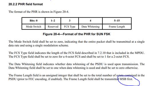
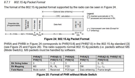
This description appears to fit well with the description in the CC1200 users guide:
The way we interpret this is that if one wishes to transmit an 802.15.4g compliant PHY frame with no whitening, with 32bit CRC, and containing 27 bytes payload the frame should be formatted thus:
00D841ECAB4E61BC0000EA1300386D040000EA1300000408015B5AE7C5
Where 00D8 is the PHY HDR with the length bit-reversed such that the length will go on the air ’MSB first’.
However in SmartRF studio 7 this frame is formattet as:
001B41ECAB4E61BC0000EA1300386D040000EA1300000408015B5AE7C5
I.e. same PHY payload, but with the length kept unchanged and so it will go on the air ’LSB first’.
A CC1200 set into 802.15.4g mode can receive both these frames, but the built-in HW accelerator only terminates the receiver after a total of 29 bytes measured from the sync word in the latter of the two examples. In the first example the receiver will continue receiving until a total of 218 bytes are received.
The question is whether our interpretation of the length field formatting is wrong or if there is a flaw in the CC1200 802.15.4g HW accelerator?
To get a second source we have tried to send 802.15.4g frames from a Silabs Si446x evaluation kit (which also states that it is 802.15.4g compliant).
Frames from this device used the same ‘MSB First’ interpretation of the PHY Frame Length that we had - and so the opposite to the CC1200.
Can you confirm either that this feature in the CC1200 is broken or somehow convince us that we are interpreting this all wrong?
Our cc1200 settings for the evaluation kit generated from SmartRF studio 7 are as follows for: [100kbps at 870MHz with 208,3KHz RxWindow].
The important values we assume are in PKT_CFG0 and PKT_CFG2:
// Rf settings for CC1200
RF_SETTINGS code rfSettings = {
0x06, // IOCFG2 GPIO2 IO Pin Configuration
0x6F, // SYNC3 Sync Word Configuration [31:24]
0x4E, // SYNC2 Sync Word Configuration [23:16]
0x90, // SYNC1 Sync Word Configuration [15:8]
0x4E, // SYNC0 Sync Word Configuration [7:0]
0xE8, // SYNC_CFG1 Sync Word Detection Configuration Reg. 1
0x23, // SYNC_CFG0 Sync Word Detection Configuration Reg. 0
0x48, // DEVIATION_M Frequency Deviation Configuration
0x0C, // MODCFG_DEV_E Modulation Format and Frequency Deviation Configur..
0x56, // DCFILT_CFG Digital DC Removal Configuration
0xBA, // PREAMBLE_CFG0 Preamble Detection Configuration Reg. 0
0x48, // IQIC Digital Image Channel Compensation Configuration
0x82, // CHAN_BW Channel Filter Configuration
0x42, // MDMCFG1 General Modem Parameter Configuration Reg. 1
0x05, // MDMCFG0 General Modem Parameter Configuration Reg. 0
0xA4, // SYMBOL_RATE2 Symbol Rate Configuration Exponent and Mantissa [1..
0x7A, // SYMBOL_RATE1 Symbol Rate Configuration Mantissa [15:8]
0xE1, // SYMBOL_RATE0 Symbol Rate Configuration Mantissa [7:0]
0x2A, // AGC_REF AGC Reference Level Configuration
0xF1, // AGC_CS_THR Carrier Sense Threshold Configuration
0x11, // AGC_CFG1 Automatic Gain Control Configuration Reg. 1
0x90, // AGC_CFG0 Automatic Gain Control Configuration Reg. 0
0x00, // FIFO_CFG FIFO Configuration
0x12, // FS_CFG Frequency Synthesizer Configuration
0x24, // PKT_CFG2 Packet Configuration Reg. 2
0x20, // PKT_CFG0 Packet Configuration Reg. 0
0x52, // PA_CFG0 Power Amplifier Configuration Reg. 0
0xFF, // PKT_LEN Packet Length Configuration
0x18, // IF_MIX_CFG IF Mix Configuration
0x03, // TOC_CFG Timing Offset Correction Configuration
0x02, // MDMCFG2 General Modem Parameter Configuration Reg. 2
0x57, // FREQ2 Frequency Configuration [23:16]
0xEE, // IF_ADC1 Analog to Digital Converter Configuration Reg. 1
0x10, // IF_ADC0 Analog to Digital Converter Configuration Reg. 0
0x04, // FS_DIG1 Frequency Synthesizer Digital Reg. 1
0x50, // FS_DIG0 Frequency Synthesizer Digital Reg. 0
0x40, // FS_CAL1 Frequency Synthesizer Calibration Reg. 1
0x0E, // FS_CAL0 Frequency Synthesizer Calibration Reg. 0
0x03, // FS_DIVTWO Frequency Synthesizer Divide by 2
0x33, // FS_DSM0 FS Digital Synthesizer Module Configuration Reg. 0
0xF7, // FS_DVC1 Frequency Synthesizer Divider Chain Configuration ..
0x0F, // FS_DVC0 Frequency Synthesizer Divider Chain Configuration ..
0x00, // FS_PFD Frequency Synthesizer Phase Frequency Detector Con..
0x6E, // FS_PRE Frequency Synthesizer Prescaler Configuration
0x1C, // FS_REG_DIV_CML Frequency Synthesizer Divider Regulator Configurat..
0xAC, // FS_SPARE Frequency Synthesizer Spare
0xB5, // FS_VCO0 FS Voltage Controlled Oscillator Configuration Reg..
0x05, // IFAMP Intermediate Frequency Amplifier Configuration
0x0E, // XOSC5 Crystal Oscillator Configuration Reg. 5
0x03, // XOSC1 Crystal Oscillator Configuration Reg. 1
0x20, // PARTNUMBER Part Number
0x10, // PARTVERSION Part Revision
0x10, // MODEM_STATUS1 Modem Status Reg. 1
};

