This thread has been locked.

If you have a related question, please click the "Ask a related question" button in the top right corner. The newly created question will be automatically linked to this question.

RTOS/LAUNCHXL-CC1310: Read data from sensor BMP280 via I2C

Part Number: LAUNCHXL-CC1310
Other Parts Discussed in Thread: CC1310, CC1350STK,

Tool/software: TI-RTOS

Hello,

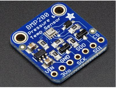
I try to change CC1310 example i2ctmp007 code to read bmp280 data.

I've already the slaveAddress from tmp007(0x40) to 0x77, but I still can't get any data.

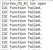
The function i2c_transfer() return bool is always false.

Is there anything I need to do?

Thank you in advance,

Best Regards,

youyun

Below are my code.

#define BMP280_ADDR 0x77
#define BMP280_REG_PRESSURE 0xF5

/* Create I2C for usage */ I2C_Params_init(&i2cParams); i2cParams.bitRate = I2C_400kHz; //i2cParams.transferMode =I2C_MODE_CALLBACK; //I2C_MODE_CALLBACK I2C_MODE_BLOCKING //i2cParams.transferCallbackFxn = NULL; i2c = I2C_open(0, &i2cParams); //(0,&i2cParams) if (i2c == NULL) { puts("Error Initializing I2C"); while (1); } else{ puts("i2c open"); } while(1){ //I2C read //BMP280 //txBuffer[0]=BMP280_REG_ID; i2cTransaction.writeBuf = NULL; i2cTransaction.writeCount = 0; i2cTransaction.readBuf = rxBuffer; i2cTransaction.readCount = 1; i2cTransaction.slaveAddress = Board_BMP_ADDR; if (I2C_transfer(i2c, &i2cTransaction)){ //bmpValue = sensorBmp280Convert(rxBuffer); puts("I2C Function work"); //sprintf(bmpData,"%f",bmpValue); //puts(bmpData); } else{ puts("I2C Function Failed."); } }
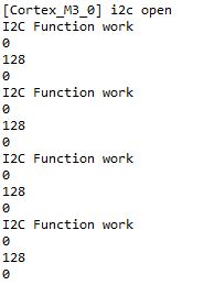
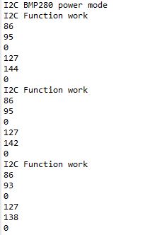
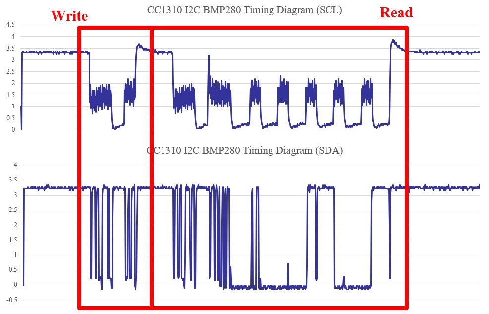
Here is the reslut.

  • Have you looked at this thread: e2e.ti.com/.../648729 ?
  • Thank for you reply.

    Yes, but the question is the function i2c_transfer() doesn't work.
    I can't catch anything from BMP280 module.
    I think I missing something have to do for reading data via i2c, but I can't find it.
    Not BMP280 module data how to calculate.

    Best Regards,
    youyun
  • Do you call “I2C_init();” before you use I2C?

  • Thank for your reply.
    Yes, I call "I2C_init();" before I use I2C.
    Sorry I didn't show that in the picture.

    Best Regards,
    youyun
  • Do you do pull-high to your I2C SCL and SDA pins? And, why do you set writeBuf=null and writeCount=0? I suppose there should be command bytes even you want to do read from bmp280.
  • Thank for your reply.
    How to pull-high the I2C SCL and SDA pins?
    Is that use function i2c_init() or use function PIN_setOutputValue()?
    I used function PIN_setOutputValue() to set SCL(pin4) and SDA(pin5) in high, but this work make function i2c_open() failed.
    Is that have any other function to use?

    Best Regards,
    youyun
  • I mean to do pull-high on your phisical I2C pins as it is in the following CC1350STK schematic.

  • Thank for your reply.
    I try it. It didn't work.
    Is that really need?

    Best Regards,
    youyun
  • It's recommended to do pull-high. And, why do you set writeBuf=null and writeCount=0? I suppose there should be command bytes even you want to do read from bmp280.
  • Thank for your reply.

    i change my code like below.

    txBuffer[0]= 0x0001;
    i2cTransaction.writeBuf = txBuffer;
    i2cTransaction.writeCount = 1;
    i2cTransaction.readBuf = rxBuffer;
    i2cTransaction.readCount = 1;
    i2cTransaction.slaveAddress = Board_BMP_ADDR;

    but it still doesn't work.

    Best Regards,

    youyun

  • Tyr to use scope to check if there is signal on SCK and SDA pins when you test this.
  • Why have you set

    i2cTransaction.writeCount = 0;

    In the thread I linked to you see code snippets from a user that got the communication up and running .
  • Thank for you reply.

    I went back to read BMP280 datasheet again. Here are the method to read the data.

    So, I change my code like below. I think my BMP280 slaveaddress is correct.

    And the register address is change like the picture show.

    But I still can't make the function I2C_transfer() return true.

    void *mainThread(void *arg0)

    {

    //I2C
    I2C_Handle i2c;
    I2C_Params i2cParams;
    I2C_Transaction i2cTransaction;
    //BMP280
    uint8_t txBuffer[1];
    uint8_t rxBuffer[2];

    /* Call driver init functions */
    GPIO_init();
    I2C_init();

    /* Configure the LED pin */
    GPIO_setConfig(Board_GPIO_LED0, GPIO_CFG_OUT_STD | GPIO_CFG_OUT_LOW);

    /* Create I2C for usage */
    I2C_Params_init(&i2cParams);
    i2cParams.bitRate = I2C_400kHz;
    //i2cParams.transferMode =I2C_MODE_CALLBACK; //I2C_MODE_CALLBACK I2C_MODE_BLOCKING
    //i2cParams.transferCallbackFxn = NULL;
    i2c = I2C_open(0, &i2cParams); 
    if (i2c == NULL) {
    puts("Error Initializing I2C");
    while (1);
    }
    else{
    puts("i2c open");
    }

    while(1){

    //I2C read (BMP280)

    txBuffer[0]= BMP280_REG_PRESSURE; //BMP280_REG_PRESSURE value is 0xF6
    i2cTransaction.slaveAddress = BMP280_ADDR; //BMP280_ADDR value is 0x77
    i2cTransaction.writeBuf = txBuffer;
    i2cTransaction.writeCount = 1;
    i2cTransaction.readBuf = rxBuffer;
    i2cTransaction.readCount = 2;

    if (I2C_transfer(i2c, &i2cTransaction)){
    puts("I2C Function work");
    }
    else{
    puts("I2C Function Failed.");
    }

    }

    Any help will be greatly appreciated!

    Best Regards,

    youyun

  • Do you still see "I2C Function Failed."? If so, do you use scope to check if there is any signal on I2C SCK and SDA pins?
  • Thank for you reply.
    Yes, I still see "I2C Function Failed.".
    Because I have to take some time to borrow the scope, I want to check the code first.
    Is that my code have any problem?

    Best Regards,
    youyun
  • Your codes look fine to me.
  • Thank for you reply.

    After using scope, I found out that slaveaddress isn't work in 0x77.

    I change the slaveaddress to 0x76 and i2c_transfer() is work.

    But the waveform aren't the same as when I connect the sensor to Arduino.

    The picture below is bmp280 connect to arduino and CC1310.

    The two picture waveform aren't the same.

    The SCL part is pretty different between two of them.

    How should I do?

    Anything suggest?

    BMP280 connet to Arduino.

    BMP280 connect to CC1310.

    Best Regards,

    youyun

  • Do you add pull-high between CC1310 and BMP280?
  • Is it a launchpad or a custom board you are using with CC1310?
  • Thank for you reply.
    I use launchpad-CC1310.
    Using launchpad Uio4 and Dio5 connect bmp280.

    Best Regards,
    youyun
  • Do you add pull-high between LAUNCHXL-CC1310 DIO_4/DIO_5 and BMP280?
  • Thank for you reply.

    Yes, I try to add pull-high between LAUNCHXL-CC1310 DIO_4/DIO_5 and BMP280.

    But the result is the same like the waveform show in the picture. Any suggestion?

    And now I have another problem. 

    Read BMP280 memory map I found out that I only catch the reset state.

    What should I do?

    Best Regards,

    youyun

    Below picture is BMP280 Timing Diagram.

    Below is BMP280 memory map.

    Below is my code.

    void *mainThread(void *arg0)
    {
        unsigned int    i;
        //I2C
        I2C_Handle      i2c;
        I2C_Params      i2cParams;
        I2C_Transaction i2cTransaction;
        //BMP280
        uint8_t    txBuffer[1];
        uint8_t    rxBuffer[2];
        float bmpValue;
        char bmpData[32];
        bool test;
    
        /* Call driver init functions */
        GPIO_init();
        I2C_init();
    
        /* Configure the LED pin */
        GPIO_setConfig(Board_GPIO_LED0, GPIO_CFG_OUT_STD | GPIO_CFG_OUT_LOW);
    
        /* Create I2C for usage */
        I2C_Params_init(&i2cParams);
        i2cParams.bitRate = I2C_400kHz;
        //i2cParams.transferMode =I2C_MODE_CALLBACK; //I2C_MODE_CALLBACK I2C_MODE_BLOCKING
        //i2cParams.transferCallbackFxn = NULL;
        i2c = I2C_open(0, &i2cParams);      //(0,&i2cParams)
        if (i2c == NULL) {
            puts("Error Initializing I2C");
            while (1);
        }
        else{
            puts("i2c open");
        }
    
        while(1){
            //I2C read
            //BMP280
            //txBuffer[0]=BMP280_REG_ID;
            txBuffer[0]= BMP280_REG_PRESSURE;       //BMP280_REG_PRESSURE value is 0xF6
            i2cTransaction.slaveAddress = BMP280_ADDR;  //BMP280_ADDR value is 0x76
            i2cTransaction.writeBuf = txBuffer;
            i2cTransaction.writeCount = 1;
            i2cTransaction.readBuf = rxBuffer;
            i2cTransaction.readCount = 2;
    
    
            for(i=0;i<100;i++){
            if (I2C_transfer(i2c, &i2cTransaction)){
                //bmpValue = sensorBmp280Convert(rxBuffer);
                puts("I2C Function work");
    
                sprintf(bmpData,"%d",rxBuffer[0]);  //0xF6 data
                puts(bmpData);
                sprintf(bmpData,"%d",rxBuffer[1]);  //0xF7 data
                puts(bmpData);
                sprintf(bmpData,"%d",rxBuffer[2]);  //0xF8 data
                puts(bmpData);
            }
            else{
                puts("I2C Function Failed.");
            }
            }
    
        }

    Below is the result.

  • I assume that you have the BMP280 on a PCB, is that correct?
  • Thank for you reply.

    Yes, I have the BMP280 on a PCB.

    Best Regards,

    youyun

  • This board is from adafruit with a regulator, some 5 V <-> 3.3 V conversion. From what I see from the schematic for this board the pin row row is on the 5 V domain. Have you review the schematic and checked how the extra components on the board impact the communication?
  • Thank for you reply.

    I read the Bmp280 datasheet again and found out that getting the sensor data needs to i2c write function first.

    I added the code like below picture and I caught the data from sensor succeed.

    But i2c timing diagram still a lot of different between the CC1310 and arduino.

    After I read the bmp280 calculate way which TER post the link, I still don't know how to do.

    Any suggestion?

    Best Regards,

    youyun

    Here is my code.

    //BMP280
    #define BMP280_ADDR 0x76    //0x76 & 0x77 
    #define BMP280_REG_PRESSURE 0xF7
    #define BMP280_REG_CTRL 0xF4
    #define BMP280_REG_TEMPATURE    0xFA
    #define BMP280_WorkMode 0x27    //0x27 temp[2:0]=001 press[2:0]=001 mode[1:0]=11(normal mode)
    #define BMP280_REG_ID 0xD0
    #define BMP280_CHIPID 0x58
    
    void *mainThread(void *arg0)
    {
        //I2C
        I2C_Handle      i2c;
        I2C_Params      i2cParams;
        I2C_Transaction i2cTransaction;
        //BMP280
        uint8_t    txBuffer[2];
        uint8_t    rxBuffer[6];
        char bmpData[32];
    
        I2C_init();
    
        /* Create I2C for usage */
        I2C_Params_init(&i2cParams);
        i2cParams.bitRate = I2C_400kHz;
        //i2cParams.transferMode =I2C_MODE_CALLBACK; //I2C_MODE_CALLBACK I2C_MODE_BLOCKING
        //i2cParams.transferCallbackFxn = NULL;
        i2c = I2C_open(0, &i2cParams);      //(0,&i2cParams)
        if (i2c == NULL) {
            puts("Error Initializing I2C");
            while (1);
        }
        else{
            puts("i2c open");
        }
    
        while(1){
            //I2C write
            //BMP280 power mode change
            //control register 0xF4
            txBuffer[0]= BMP280_REG_CTRL;
            txBuffer[1]= BMP280_WorkMode;
            i2cTransaction.slaveAddress = BMP280_ADDR;
            i2cTransaction.writeBuf = txBuffer;
            i2cTransaction.writeCount = 2;
            i2cTransaction.readBuf = rxBuffer;
            i2cTransaction.readCount = 0;
    
            if (I2C_transfer(i2c, &i2cTransaction)){
                puts("I2C BMP280 power mode");
            }
    
            //I2C read
            //BMP280 memory map pressure to temperature
            txBuffer[0]= BMP280_REG_PRESSURE;       //BMP280_REG_PRESSURE value is 0xF6
            i2cTransaction.slaveAddress = BMP280_ADDR;  //BMP280_ADDR value is 0x76
            i2cTransaction.writeBuf = txBuffer;
            i2cTransaction.writeCount = 1;
            i2cTransaction.readBuf = rxBuffer;
            i2cTransaction.readCount = 6;
    
            for(i=0;i<1000;i++){
            if (I2C_transfer(i2c, &i2cTransaction)){
                //bmpValue = sensorBmp280Convert(rxBuffer);
                puts("I2C Function work");
    
                sprintf(bmpData,"%d",rxBuffer[0]);  //0xF7 data press_msb
                puts(bmpData);
                sprintf(bmpData,"%d",rxBuffer[1]);  //0xF8 data press_lsb
                puts(bmpData);
                sprintf(bmpData,"%d",rxBuffer[2]);  //0xF9 data press_xlsb oversampling
                puts(bmpData);
                sprintf(bmpData,"%d",rxBuffer[3]);  //0xFA data temperature_msb
                puts(bmpData);
                sprintf(bmpData,"%d",rxBuffer[4]);  //0xFB data temperature_lsb
                puts(bmpData);
                sprintf(bmpData,"%d",rxBuffer[5]);  //0xFC data temperature_xlsb oversampling
                puts(bmpData);
    
            }
            else{
                puts("I2C Function Failed.");
            }
            }
    
        }

    The data I caught from bmp280.

    The bmp280 timing diagram on cc1310.

    The timing diagram of arduino and cc1310.

  • As far as I can see you are not addressing my question:

    "This board is from adafruit with a regulator, some 5 V <-> 3.3 V conversion. From what I see from the schematic for this board the pin row row is on the 5 V domain. Have you review the schematic and checked how the extra components on the board impact the communication?"

    Before starting to look into the software you have to fully understand the hardware.