Tool/software: TI-RTOS
Hello, I use TX an RX examples to do my follow code:
#include <unistd.h>
#include <stdint.h>
#include <stddef.h>
#include <stdlib.h>
/* Driver Header files */
#include <ti/drivers/rf/RF.h>
// #include <ti/drivers/GPIO.h>
#include <ti/drivers/PIN.h>
#include <ti/drivers/pin/PINCC26XX.h>
#include <ti/drivers/timer/GPTimerCC26XX.h>
// #include <ti/drivers/I2C.h>
// #include <ti/drivers/SDSPI.h>
// #include <ti/drivers/SPI.h>
// #include <ti/drivers/UART.h>
// #include <ti/drivers/Watchdog.h>
/* Driverlib Header files */
#include DeviceFamily_constructPath(driverlib/rf_prop_mailbox.h)
/* Board Header file */
#include "Board.h"
#include "RFQueue.h"
#include "smartrf_settings_433MHz/smartrf_settings.h"
#define PAYLOAD_LENGTH 30
/* Packet RX Configuration */
#define DATA_ENTRY_HEADER_SIZE 8 /* Constant header size of a Generic Data Entry */
#define MAX_LENGTH 30 /* Max length byte the radio will accept */
#define NUM_DATA_ENTRIES 2 /* NOTE: Only two data entries supported at the moment */
#define NUM_APPENDED_BYTES 2 /* The Data Entries data field will contain:
* 1 Header byte (RF_cmdPropRx.rxConf.bIncludeHdr = 0x1)
* Max 30 payload bytes
* 1 status byte (RF_cmdPropRx.rxConf.bAppendStatus = 0x1) */
static void callback(RF_Handle h, RF_CmdHandle ch, RF_EventMask e);
static RF_Object rfObject;
static RF_Handle rfHandle;
static PIN_Handle ledPinHandle;
static PIN_State ledPinState;
/* Buffer which contains all Data Entries for receiving data.
* Pragmas are needed to make sure this buffer is 4 byte aligned (requirement from the RF Core) */
#pragma DATA_ALIGN (rxDataEntryBuffer, 4);
static uint8_t rxDataEntryBuffer[RF_QUEUE_DATA_ENTRY_BUFFER_SIZE(NUM_DATA_ENTRIES, MAX_LENGTH, NUM_APPENDED_BYTES)];
/* Receive dataQueue for RF Core to fill in data */
static dataQueue_t dataQueue;
static rfc_dataEntryGeneral_t* currentDataEntry;
static uint8_t packetLength;
static uint8_t* packetDataPointer;
static uint8_t packet[MAX_LENGTH + NUM_APPENDED_BYTES - 1]; /* The length byte is stored in a separate variable */
//static uint8_t packet[PAYLOAD_LENGTH];
static uint16_t seqNumber;
PIN_Config pinTable[] =
{
Board_PIN_LED1 | PIN_GPIO_OUTPUT_EN | PIN_GPIO_LOW | PIN_PUSHPULL | PIN_DRVSTR_MAX,
Board_PIN_LED2 | PIN_GPIO_OUTPUT_EN | PIN_GPIO_LOW | PIN_PUSHPULL | PIN_DRVSTR_MAX,
PIN_TERMINATE
};
static int accion;
//accion=0 (transmision)
//accion=1 (recepcion)
/*
* ======== mainThread ========
*/
void *taskLedToggleTimer(void *arg0)
{
/* Call driver init functions */
RF_Params rfParams;
RF_Params_init(&rfParams);
ledPinHandle = PIN_open(&ledPinState, pinTable);
if (ledPinHandle == NULL) {
while(1);
}
if(RFQueue_defineQueue(&dataQueue, rxDataEntryBuffer, sizeof(rxDataEntryBuffer), NUM_DATA_ENTRIES, MAX_LENGTH + NUM_APPENDED_BYTES)) {
/* Failed to allocate space for all data entries */
while(1);
}
RF_cmdPropTx.pktLen = PAYLOAD_LENGTH;
RF_cmdPropTx.pPkt = packet;
RF_cmdPropTx.startTrigger.triggerType = TRIG_NOW;
/* Modify CMD_PROP_RX command for application needs */
/* Set the Data Entity queue for received data */
RF_cmdPropRx.pQueue = &dataQueue;
/* Discard ignored packets from Rx queue */
RF_cmdPropRx.rxConf.bAutoFlushIgnored = 1;
/* Discard packets with CRC error from Rx queue */
RF_cmdPropRx.rxConf.bAutoFlushCrcErr = 1;
/* Implement packet length filtering to avoid PROP_ERROR_RXBUF */
RF_cmdPropRx.maxPktLen = PAYLOAD_LENGTH;
RF_cmdPropRx.pktConf.bRepeatOk = 0;
RF_cmdPropRx.pktConf.bRepeatNok = 0;
/* Request access to the radio */
rfHandle = RF_open(&rfObject, &RF_prop, (RF_RadioSetup*)&RF_cmdPropRadioDivSetup, &rfParams);
/* Set the frequency */
RF_postCmd(rfHandle, (RF_Op*)&RF_cmdFs, RF_PriorityNormal, NULL, 0);
accion = 0;
seqNumber=0;
while (1) {
if(accion == 0) {
packet[0] = (uint8_t)(seqNumber >> 8);
packet[1] = (uint8_t)(seqNumber++);
uint8_t i;
for (i = 2; i < PAYLOAD_LENGTH; i++) {
packet[i] = i - 2;
}
/* Send packet */
RF_EventMask terminationReason = RF_runCmd(rfHandle, (RF_Op*)&RF_cmdPropTx, RF_PriorityNormal, NULL, 0);
switch(terminationReason) {
case RF_EventLastCmdDone:
// A stand-alone radio operation command or the last radio
// operation command in a chain finished.
break;
case RF_EventCmdCancelled:
// Command cancelled before it was started; it can be caused
// by RF_cancelCmd() or RF_flushCmd().
break;
case RF_EventCmdAborted:
// Abrupt command termination caused by RF_cancelCmd() or
// RF_flushCmd().
break;
case RF_EventCmdStopped:
// Graceful command termination caused by RF_cancelCmd() or
// RF_flushCmd().
break;
default:
// Uncaught error event
while(1);
}
uint32_t cmdStatus = ((volatile RF_Op*)&RF_cmdPropTx)->status;
switch(cmdStatus) {
case PROP_DONE_OK:
// Packet transmitted successfully
PIN_setOutputValue(ledPinHandle, Board_PIN_LED1,!PIN_getOutputValue(Board_PIN_LED1));
accion=1;
break;
case PROP_DONE_STOPPED:
// received CMD_STOP while transmitting packet and finished
// transmitting packet
break;
case PROP_DONE_ABORT:
// Received CMD_ABORT while transmitting packet
break;
case PROP_ERROR_PAR:
// Observed illegal parameter
break;
case PROP_ERROR_NO_SETUP:
// Command sent without setting up the radio in a supported
// mode using CMD_PROP_RADIO_SETUP or CMD_RADIO_SETUP
break;
case PROP_ERROR_NO_FS:
// Command sent without the synthesizer being programmed
break;
case PROP_ERROR_TXUNF:
// TX underflow observed during operation
break;
default:
// Uncaught error event - these could come from the
// pool of states defined in rf_mailbox.h
while(1);
}
}
else{
RF_EventMask terminationReason = RF_runCmd(rfHandle, (RF_Op*)&RF_cmdPropRx, RF_PriorityNormal, &callback, RF_EventRxEntryDone);
switch(terminationReason) {
case RF_EventLastCmdDone:
// A stand-alone radio operation command or the last radio
// operation command in a chain finished.
break;
case RF_EventCmdCancelled:
// Command cancelled before it was started; it can be caused
// by RF_cancelCmd() or RF_flushCmd().
break;
case RF_EventCmdAborted:
// Abrupt command termination caused by RF_cancelCmd() or
// RF_flushCmd().
break;
case RF_EventCmdStopped:
// Graceful command termination caused by RF_cancelCmd() or
// RF_flushCmd().
break;
default:
// Uncaught error event
while(1);
}
uint32_t cmdStatus = ((volatile RF_Op*)&RF_cmdPropRx)->status;
switch(cmdStatus) {
case PROP_DONE_OK:
// Packet received with CRC OK
/* Toggle pin to indicate RX */
PIN_setOutputValue(ledPinHandle, Board_PIN_LED2, !PIN_getOutputValue(Board_PIN_LED2));
accion=0;
sleep(1);
break;
case PROP_DONE_RXERR:
// Packet received with CRC error
break;
case PROP_DONE_RXTIMEOUT:
// Observed end trigger while in sync search
break;
case PROP_DONE_BREAK:
// Observed end trigger while receiving packet when the command is
// configured with endType set to 1
break;
case PROP_DONE_ENDED:
// Received packet after having observed the end trigger; if the
// command is configured with endType set to 0, the end trigger
// will not terminate an ongoing reception
break;
case PROP_DONE_STOPPED:
// received CMD_STOP after command started and, if sync found,
// packet is received
break;
case PROP_DONE_ABORT:
// Received CMD_ABORT after command started
break;
case PROP_ERROR_RXBUF:
// No RX buffer large enough for the received data available at
// the start of a packet
break;
case PROP_ERROR_RXFULL:
// Out of RX buffer space during reception in a partial read
break;
case PROP_ERROR_PAR:
// Observed illegal parameter
break;
case PROP_ERROR_NO_SETUP:
// Command sent without setting up the radio in a supported
// mode using CMD_PROP_RADIO_SETUP or CMD_RADIO_SETUP
break;
case PROP_ERROR_NO_FS:
// Command sent without the synthesizer being programmed
break;
case PROP_ERROR_RXOVF:
// RX overflow observed during operation
break;
default:
// Uncaught error event - these could come from the
// pool of states defined in rf_mailbox.h
while(1);
}
}
}
}
void callback(RF_Handle h, RF_CmdHandle ch, RF_EventMask e)
{
if (e & RF_EventRxEntryDone)
{
/* Get current unhandled data entry */
currentDataEntry = RFQueue_getDataEntry();
/* Handle the packet data, located at ¤tDataEntry->data:
* - Length is the first byte with the current configuration
* - Data starts from the second byte */
packetLength = *(uint8_t*)(¤tDataEntry->data);
packetDataPointer = (uint8_t*)(¤tDataEntry->data + 1);
/* Copy the payload + the status byte to the packet variable */
memcpy(packet, packetDataPointer, (packetLength + 1));
RFQueue_nextEntry();
}
}
When I use this code in two launchpad my code work OK, in my first launchpad "action = 1" and in the second "action = 0", I using smartrf_settings.c
#include <ti/devices/DeviceFamily.h>
#include DeviceFamily_constructPath(driverlib/rf_mailbox.h)
#include DeviceFamily_constructPath(driverlib/rf_common_cmd.h)
#include DeviceFamily_constructPath(driverlib/rf_prop_cmd.h)
#include <ti/drivers/rf/RF.h>
#include DeviceFamily_constructPath(rf_patches/rf_patch_cpe_genfsk.h)
#include DeviceFamily_constructPath(rf_patches/rf_patch_rfe_genfsk.h)
#include "smartrf_settings.h"


// TI-RTOS RF Mode Object
RF_Mode RF_prop =
{
    .rfMode = RF_MODE_PROPRIETARY_SUB_1,
    .cpePatchFxn = &rf_patch_cpe_genfsk,
    .mcePatchFxn = 0,
    .rfePatchFxn = &rf_patch_rfe_genfsk,
};

// Overrides for CMD_PROP_RADIO_DIV_SETUP
uint32_t pOverrides[] =
{
    // override_use_patch_prop_genfsk.xml
    // PHY: Use MCE ROM bank 4, RFE RAM patch
    MCE_RFE_OVERRIDE(0,4,0,1,0,0),
    // override_synth_prop_863_930_div5.xml
    // Synth: Set recommended RTRIM to 7
    HW_REG_OVERRIDE(0x4038,0x0037),
    // Synth: Set Fref to 4 MHz
    (uint32_t)0x000684A3,
    // Synth: Configure fine calibration setting
    HW_REG_OVERRIDE(0x4020,0x7F00),
    // Synth: Configure fine calibration setting
    HW_REG_OVERRIDE(0x4064,0x0040),
    // Synth: Configure fine calibration setting
    (uint32_t)0xB1070503,
    // Synth: Configure fine calibration setting
    (uint32_t)0x05330523,
    // Synth: Set loop bandwidth after lock to 20 kHz
    (uint32_t)0x0A480583,
    // Synth: Set loop bandwidth after lock to 20 kHz
    (uint32_t)0x7AB80603,
    // Synth: Configure VCO LDO (in ADI1, set VCOLDOCFG=0x9F to use voltage input reference)
    ADI_REG_OVERRIDE(1,4,0x9F),
    // Synth: Configure synth LDO (in ADI1, set SLDOCTL0.COMP_CAP=1)
    ADI_HALFREG_OVERRIDE(1,7,0x4,0x4),
    // Synth: Use 24 MHz XOSC as synth clock, enable extra PLL filtering
    (uint32_t)0x02010403,
    // Synth: Configure extra PLL filtering
    (uint32_t)0x00108463,
    // Synth: Increase synth programming timeout (0x04B0 RAT ticks = 300 us)
    (uint32_t)0x04B00243,
    // override_phy_rx_aaf_bw_0xd.xml
    // Rx: Set anti-aliasing filter bandwidth to 0xD (in ADI0, set IFAMPCTL3[7:4]=0xD)
    ADI_HALFREG_OVERRIDE(0,61,0xF,0xD),
    // override_phy_gfsk_rx.xml
    // Rx: Set LNA bias current trim offset to 3
    (uint32_t)0x00038883,
    // Rx: Freeze RSSI on sync found event
    HW_REG_OVERRIDE(0x6084,0x35F1),
    // override_phy_gfsk_pa_ramp_agc_reflevel_0x1a.xml
    // Tx: Configure PA ramping setting (0x41). Rx: Set AGC reference level to 0x1A.
    HW_REG_OVERRIDE(0x6088,0x411A),
    // Tx: Configure PA ramping setting
    HW_REG_OVERRIDE(0x608C,0x8213),
    // override_phy_rx_rssi_offset_5db.xml
    // Rx: Set RSSI offset to adjust reported RSSI by +5 dB (default: 0), trimmed for external bias and differential configuration
    (uint32_t)0x00FB88A3,
#if (CCFG_FORCE_VDDR_HH)
    // TX power override
    // Tx: Set PA trim to max (in ADI0, set PACTL0=0xF8)
    ADI_REG_OVERRIDE(0,12,0xF8),
#endif
    (uint32_t)0xFFFFFFFF,
};


// CMD_PROP_RADIO_DIV_SETUP
rfc_CMD_PROP_RADIO_DIV_SETUP_t RF_cmdPropRadioDivSetup =
{
    .commandNo = 0x3807,
    .status = 0x0000,
    .pNextOp = 0, // INSERT APPLICABLE POINTER: (uint8_t*)&xxx
    .startTime = 0x00000000,
    .startTrigger.triggerType = 0x0,
    .startTrigger.bEnaCmd = 0x0,
    .startTrigger.triggerNo = 0x0,
    .startTrigger.pastTrig = 0x0,
    .condition.rule = 0x1,
    .condition.nSkip = 0x0,
    .modulation.modType = 0x1,
    .modulation.deviation = 0x64,
    .symbolRate.preScale = 0xF,
    .symbolRate.rateWord = 0x8000,
    .symbolRate.decimMode = 0x0,
    .rxBw = 0x24,
    .preamConf.nPreamBytes = 0x4,
    .preamConf.preamMode = 0x0,
    .formatConf.nSwBits = 0x20,
    .formatConf.bBitReversal = 0x0,
    .formatConf.bMsbFirst = 0x1,
    .formatConf.fecMode = 0x0,
    .formatConf.whitenMode = 0x0,
    .config.frontEndMode = 0x0,
    .config.biasMode = 0x1,
    .config.analogCfgMode = 0x0,
    .config.bNoFsPowerUp = 0x0,
    .txPower = 0xA73F,
    .pRegOverride = pOverrides,
    .centerFreq = 0x0364,
    .intFreq = 0x8000,
    .loDivider = 0x05,
};

// CMD_FS
rfc_CMD_FS_t RF_cmdFs =
{
    .commandNo = 0x0803,
    .status = 0x0000,
    .pNextOp = 0, // INSERT APPLICABLE POINTER: (uint8_t*)&xxx
    .startTime = 0x00000000,
    .startTrigger.triggerType = 0x0,
    .startTrigger.bEnaCmd = 0x0,
    .startTrigger.triggerNo = 0x0,
    .startTrigger.pastTrig = 0x0,
    .condition.rule = 0x1,
    .condition.nSkip = 0x0,
    .frequency = 0x0364,
    .fractFreq = 0x0000,
    .synthConf.bTxMode = 0x0,
    .synthConf.refFreq = 0x0,
    .__dummy0 = 0x00,
    .__dummy1 = 0x00,
    .__dummy2 = 0x00,
    .__dummy3 = 0x0000,
};

// CMD_PROP_TX
rfc_CMD_PROP_TX_t RF_cmdPropTx =
{
    .commandNo = 0x3801,
    .status = 0x0000,
    .pNextOp = 0, // INSERT APPLICABLE POINTER: (uint8_t*)&xxx
    .startTime = 0x00000000,
    .startTrigger.triggerType = 0x0,
    .startTrigger.bEnaCmd = 0x0,
    .startTrigger.triggerNo = 0x0,
    .startTrigger.pastTrig = 0x0,
    .condition.rule = 0x1,
    .condition.nSkip = 0x0,
    .pktConf.bFsOff = 0x0,
    .pktConf.bUseCrc = 0x1,
    .pktConf.bVarLen = 0x1,
    .pktLen = 0x1E, // SET APPLICATION PAYLOAD LENGTH
    .syncWord = 0x930B51DE,
    .pPkt = 0, // INSERT APPLICABLE POINTER: (uint8_t*)&xxx
};

// CMD_PROP_RX
rfc_CMD_PROP_RX_t RF_cmdPropRx =
{
    .commandNo = 0x3802,
    .status = 0x0000,
    .pNextOp = 0, // INSERT APPLICABLE POINTER: (uint8_t*)&xxx
    .startTime = 0x00000000,
    .startTrigger.triggerType = 0x0,
    .startTrigger.bEnaCmd = 0x0,
    .startTrigger.triggerNo = 0x0,
    .startTrigger.pastTrig = 0x0,
    .condition.rule = 0x1,
    .condition.nSkip = 0x0,
    .pktConf.bFsOff = 0x0,
    .pktConf.bRepeatOk = 0x0,
    .pktConf.bRepeatNok = 0x0,
    .pktConf.bUseCrc = 0x1,
    .pktConf.bVarLen = 0x1,
    .pktConf.bChkAddress = 0x0,
    .pktConf.endType = 0x0,
    .pktConf.filterOp = 0x0,
    .rxConf.bAutoFlushIgnored = 0x0,
    .rxConf.bAutoFlushCrcErr = 0x0,
    .rxConf.bIncludeHdr = 0x1,
    .rxConf.bIncludeCrc = 0x0,
    .rxConf.bAppendRssi = 0x0,
    .rxConf.bAppendTimestamp = 0x0,
    .rxConf.bAppendStatus = 0x1,
    .syncWord = 0x930B51DE,
    .maxPktLen = 0xFF, // MAKE SURE DATA ENTRY IS LARGE ENOUGH
    .address0 = 0xAA,
    .address1 = 0xBB,
    .endTrigger.triggerType = 0x1,
    .endTrigger.bEnaCmd = 0x0,
    .endTrigger.triggerNo = 0x0,
    .endTrigger.pastTrig = 0x0,
    .endTime = 0x00000000,
    .pQueue = 0, // INSERT APPLICABLE POINTER: (dataQueue_t*)&xxx
    .pOutput = 0, // INSERT APPLICABLE POINTER: (uint8_t*)&xxx
};

// CMD_TX_TEST
rfc_CMD_TX_TEST_t RF_cmdTxTest =
{
    .commandNo = 0x0808,
    .status = 0x0000,
    .pNextOp = 0, // INSERT APPLICABLE POINTER: (uint8_t*)&xxx
    .startTime = 0x00000000,
    .startTrigger.triggerType = 0x0,
    .startTrigger.bEnaCmd = 0x0,
    .startTrigger.triggerNo = 0x0,
    .startTrigger.pastTrig = 0x0,
    .condition.rule = 0x1,
    .condition.nSkip = 0x0,
    .config.bUseCw = 0x0,
    .config.bFsOff = 0x1,
    .config.whitenMode = 0x2,
    .__dummy0 = 0x00,
    .txWord = 0xABCD,
    .__dummy1 = 0x00,
    .endTrigger.triggerType = 0x1,
    .endTrigger.bEnaCmd = 0x0,
    .endTrigger.triggerNo = 0x0,
    .endTrigger.pastTrig = 0x0,
    .syncWord = 0x930B51DE,
    .endTime = 0x00000000,
};
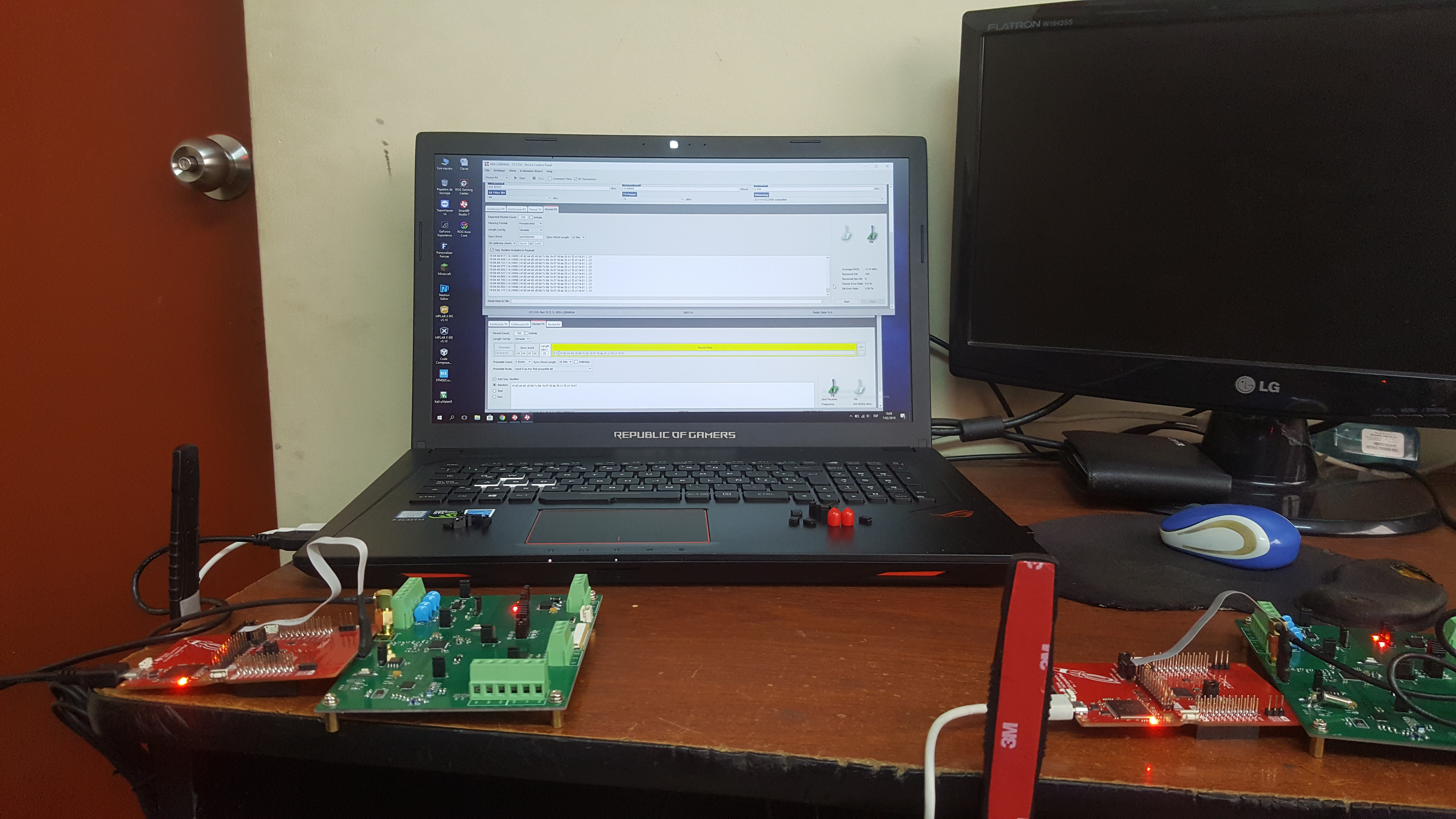
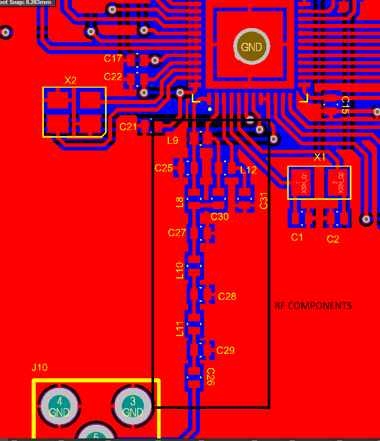
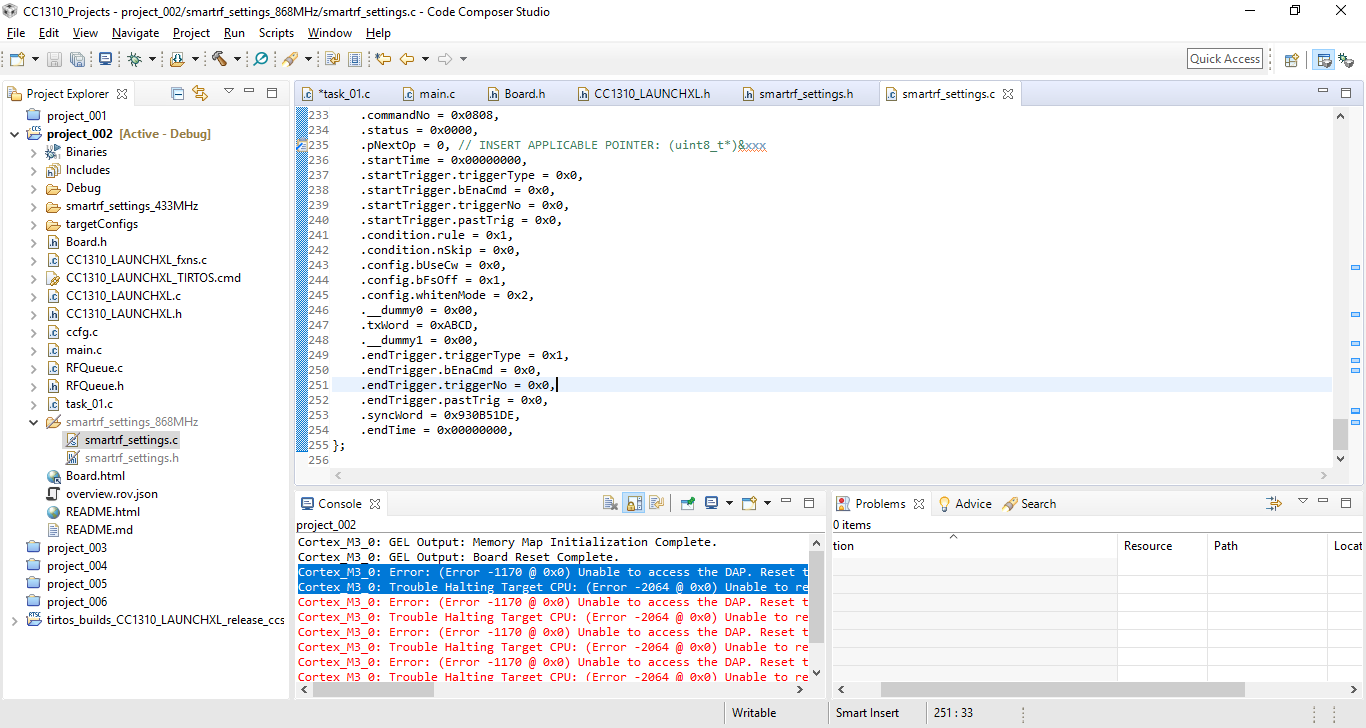
But when I use the same code in two custome boards for 433MHz, the code don´t work, the first TX (board A) and RX (board B) is OK but when the RX (Board B) try to TX I get these code in debugger
For 433MHz I use smartrf_sttings.c generated by SmartRF Studio
#include <ti/devices/DeviceFamily.h>
#include DeviceFamily_constructPath(driverlib/rf_mailbox.h)
#include DeviceFamily_constructPath(driverlib/rf_common_cmd.h)
#include DeviceFamily_constructPath(driverlib/rf_prop_cmd.h)
#include <ti/drivers/rf/RF.h>
#include DeviceFamily_constructPath(rf_patches/rf_patch_cpe_genfsk.h)
#include DeviceFamily_constructPath(rf_patches/rf_patch_rfe_genfsk.h)
#include "smartrf_settings.h"


// TI-RTOS RF Mode Object
RF_Mode RF_prop =
{
    .rfMode = RF_MODE_PROPRIETARY_SUB_1,
    .cpePatchFxn = &rf_patch_cpe_genfsk,
    .mcePatchFxn = 0,
    .rfePatchFxn = &rf_patch_rfe_genfsk,
};


// Overrides for CMD_PROP_RADIO_DIV_SETUP
uint32_t pOverrides[] =
{
    // override_use_patch_prop_genfsk.xml
    // PHY: Use MCE ROM bank 4, RFE RAM patch
    MCE_RFE_OVERRIDE(0,4,0,1,0,0),
    // override_synth_prop_430_510_div10.xml
    // Synth: Set recommended RTRIM to 7
    HW_REG_OVERRIDE(0x4038,0x0037),
    // Synth: Set Fref to 4 MHz
    (uint32_t)0x000684A3,
    // Synth: Configure fine calibration setting
    HW_REG_OVERRIDE(0x4020,0x7F00),
    // Synth: Configure fine calibration setting
    HW_REG_OVERRIDE(0x4064,0x0040),
    // Synth: Configure fine calibration setting
    (uint32_t)0xB1070503,
    // Synth: Configure fine calibration setting
    (uint32_t)0x05330523,
    // Synth: Set loop bandwidth after lock to 20 kHz
    (uint32_t)0x0A480583,
    // Synth: Set loop bandwidth after lock to 20 kHz
    (uint32_t)0x7AB80603,
    // Synth: Configure VCO LDO (in ADI1, set VCOLDOCFG=0x9F to use voltage input reference)
    ADI_REG_OVERRIDE(1,4,0x9F),
    // Synth: Configure synth LDO (in ADI1, set SLDOCTL0.COMP_CAP=1)
    ADI_HALFREG_OVERRIDE(1,7,0x4,0x4),
    // Synth: Use 24 MHz XOSC as synth clock, enable extra PLL filtering
    (uint32_t)0x02010403,
    // Synth: Configure extra PLL filtering
    (uint32_t)0x00108463,
    // Synth: Increase synth programming timeout (0x04B0 RAT ticks = 300 us)
    (uint32_t)0x04B00243,
    // override_synth_disable_bias_div10.xml
    // Synth: Set divider bias to disabled
    HW32_ARRAY_OVERRIDE(0x405C,1),
    // Synth: Set divider bias to disabled (specific for loDivider=10)
    (uint32_t)0x18000280,
    // override_phy_rx_aaf_bw_0xd.xml
    // Rx: Set anti-aliasing filter bandwidth to 0xD (in ADI0, set IFAMPCTL3[7:4]=0xD)
    ADI_HALFREG_OVERRIDE(0,61,0xF,0xD),
    // override_phy_gfsk_rx.xml
    // Rx: Set LNA bias current trim offset to 3
    (uint32_t)0x00038883,
    // Rx: Freeze RSSI on sync found event
    HW_REG_OVERRIDE(0x6084,0x35F1),
    // override_phy_gfsk_pa_ramp_agc_reflevel_0x1a.xml
    // Tx: Configure PA ramping setting (0x41). Rx: Set AGC reference level to 0x1A.
    HW_REG_OVERRIDE(0x6088,0x411A),
    // Tx: Configure PA ramping setting
    HW_REG_OVERRIDE(0x608C,0x8213),
    // override_phy_rx_rssi_offset_neg2db.xml
    // Rx: Set RSSI offset to adjust reported RSSI by -2 dB (default: 0), trimmed for external bias and differential configuration
    (uint32_t)0x000288A3,
    // TX power override
    // Tx: Set PA trim to max (in ADI0, set PACTL0=0xF8)
    ADI_REG_OVERRIDE(0,12,0xF8),
    (uint32_t)0xFFFFFFFF
};


// CMD_PROP_RADIO_DIV_SETUP
// Proprietary Mode Radio Setup Command for All Frequency Bands
rfc_CMD_PROP_RADIO_DIV_SETUP_t RF_cmdPropRadioDivSetup =
{
    .commandNo = 0x3807,
    .status = 0x0000,
    .pNextOp = 0, // INSERT APPLICABLE POINTER: (uint8_t*)&xxx
    .startTime = 0x00000000,
    .startTrigger.triggerType = 0x0,
    .startTrigger.bEnaCmd = 0x0,
    .startTrigger.triggerNo = 0x0,
    .startTrigger.pastTrig = 0x0,
    .condition.rule = 0x1,
    .condition.nSkip = 0x0,
    .modulation.modType = 0x1,
    .modulation.deviation = 0x64,
    .symbolRate.preScale = 0xF,
    .symbolRate.rateWord = 0x8000,
    .symbolRate.decimMode = 0x0,
    .rxBw = 0x24,
    .preamConf.nPreamBytes = 0x4,
    .preamConf.preamMode = 0x0,
    .formatConf.nSwBits = 0x20,
    .formatConf.bBitReversal = 0x0,
    .formatConf.bMsbFirst = 0x1,
    .formatConf.fecMode = 0x0,
    .formatConf.whitenMode = 0x0,
    .config.frontEndMode = 0x0,
    .config.biasMode = 0x1,
    .config.analogCfgMode = 0x0,
    .config.bNoFsPowerUp = 0x0,
    .txPower = 0x913F,
    .pRegOverride = pOverrides,
    .centerFreq = 0x01B1,
    .intFreq = 0x8000,
    .loDivider = 0x0A
};


// CMD_FS
// Frequency Synthesizer Programming Command
rfc_CMD_FS_t RF_cmdFs =
{
    .commandNo = 0x0803,
    .status = 0x0000,
    .pNextOp = 0, // INSERT APPLICABLE POINTER: (uint8_t*)&xxx
    .startTime = 0x00000000,
    .startTrigger.triggerType = 0x0,
    .startTrigger.bEnaCmd = 0x0,
    .startTrigger.triggerNo = 0x0,
    .startTrigger.pastTrig = 0x0,
    .condition.rule = 0x1,
    .condition.nSkip = 0x0,
    .frequency = 0x01B1,
    .fractFreq = 0xEB9A,
    .synthConf.bTxMode = 0x0,
    .synthConf.refFreq = 0x0,
    .__dummy0 = 0x00,
    .__dummy1 = 0x00,
    .__dummy2 = 0x00,
    .__dummy3 = 0x0000
};


// CMD_PROP_TX
// Proprietary Mode Transmit Command
rfc_CMD_PROP_TX_t RF_cmdPropTx =
{
    .commandNo = 0x3801,
    .status = 0x0000,
    .pNextOp = 0, // INSERT APPLICABLE POINTER: (uint8_t*)&xxx
    .startTime = 0x00000000,
    .startTrigger.triggerType = 0x0,
    .startTrigger.bEnaCmd = 0x0,
    .startTrigger.triggerNo = 0x0,
    .startTrigger.pastTrig = 0x0,
    .condition.rule = 0x1,
    .condition.nSkip = 0x0,
    .pktConf.bFsOff = 0x0,
    .pktConf.bUseCrc = 0x1,
    .pktConf.bVarLen = 0x1,
    .pktLen = 0x1E,
    .syncWord = 0x930B51DE,
    .pPkt = 0 // INSERT APPLICABLE POINTER: (uint8_t*)&xxx
};


// CMD_PROP_RX
// Proprietary Mode Receive Command
rfc_CMD_PROP_RX_t RF_cmdPropRx =
{
    .commandNo = 0x3802,
    .status = 0x0000,
    .pNextOp = 0, // INSERT APPLICABLE POINTER: (uint8_t*)&xxx
    .startTime = 0x00000000,
    .startTrigger.triggerType = 0x0,
    .startTrigger.bEnaCmd = 0x0,
    .startTrigger.triggerNo = 0x0,
    .startTrigger.pastTrig = 0x0,
    .condition.rule = 0x1,
    .condition.nSkip = 0x0,
    .pktConf.bFsOff = 0x0,
    .pktConf.bRepeatOk = 0x0,
    .pktConf.bRepeatNok = 0x0,
    .pktConf.bUseCrc = 0x1,
    .pktConf.bVarLen = 0x1,
    .pktConf.bChkAddress = 0x0,
    .pktConf.endType = 0x0,
    .pktConf.filterOp = 0x0,
    .rxConf.bAutoFlushIgnored = 0x0,
    .rxConf.bAutoFlushCrcErr = 0x0,
    .rxConf.bIncludeHdr = 0x1,
    .rxConf.bIncludeCrc = 0x0,
    .rxConf.bAppendRssi = 0x0,
    .rxConf.bAppendTimestamp = 0x0,
    .rxConf.bAppendStatus = 0x1,
    .syncWord = 0x930B51DE,
    .maxPktLen = 0xFF,
    .address0 = 0xAA,
    .address1 = 0xBB,
    .endTrigger.triggerType = 0x1,
    .endTrigger.bEnaCmd = 0x0,
    .endTrigger.triggerNo = 0x0,
    .endTrigger.pastTrig = 0x0,
    .endTime = 0x00000000,
    .pQueue = 0, // INSERT APPLICABLE POINTER: (dataQueue_t*)&xxx
    .pOutput = 0 // INSERT APPLICABLE POINTER: (uint8_t*)&xxx
};