This thread has been locked.

If you have a related question, please click the "Ask a related question" button in the top right corner. The newly created question will be automatically linked to this question.

CCS/CC1310: The issue of failing to debug my customed target with CC1310F64

Part Number: CC1310

Tool/software: Code Composer Studio

Hello everyone,

I'm meeting an difficulty of debugging an used project in a new target board which is based on the identical schematic chart and PCB layout as an old target board. In order to describle the situation clearly, an introduction of my debugging environment and a procedure of debugging the new and old target boards are presented below.

Introduction:

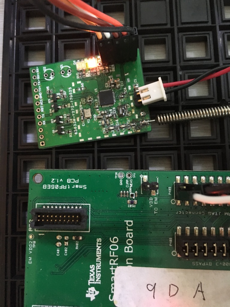
I use two SmartRF06EVMs debugging external an external, self-powered target.

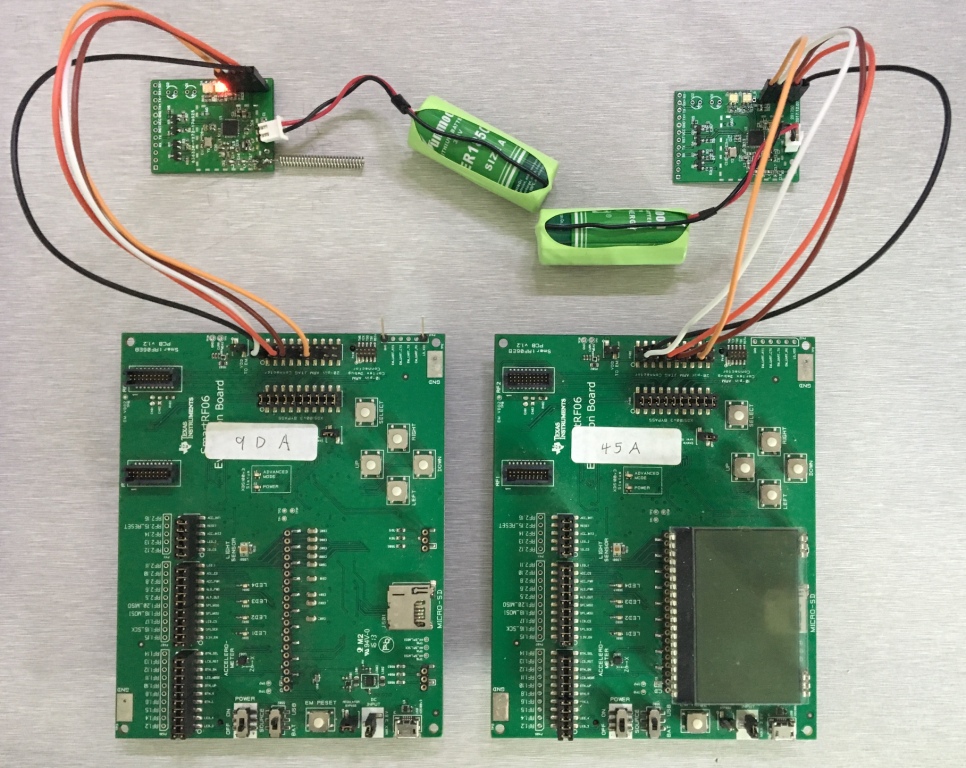
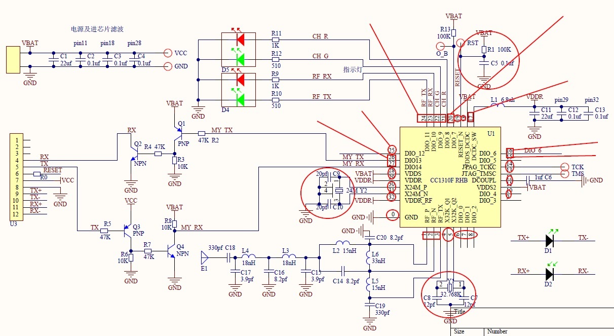
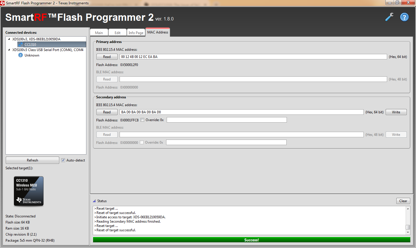
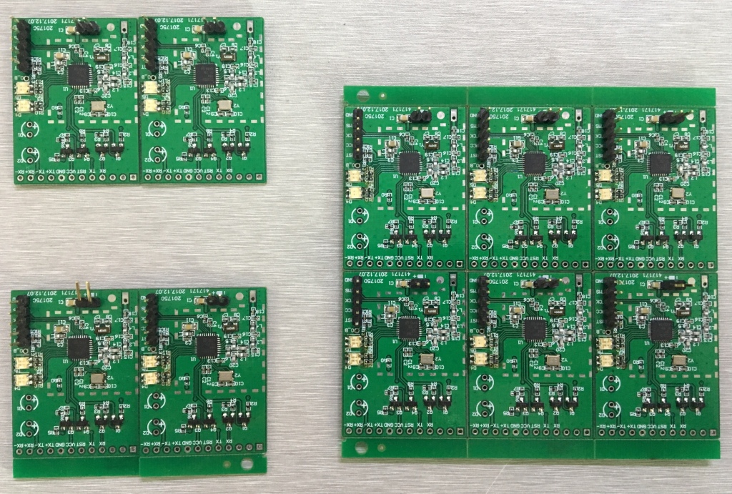
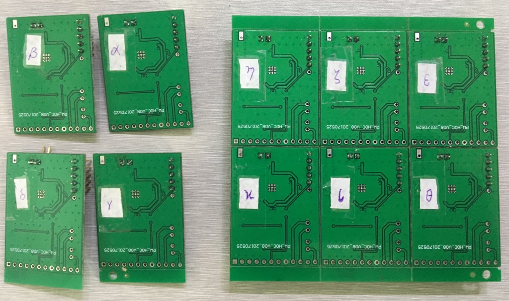
There are ten new targets and an old target with an antenna, which are customed boards with CC1310F64(IC revisions is B(2.1)).

Procedure:

I made a compare test with a new target (I altered the new target from the others, did it nine times, got same results) and the old target. The procedure includes six steps as below.

1)I debug my project in the old target by CCS. My program runs well, such as lighting some LEDs.

2)When I debug my project in the chosen new target, a message is indicated as "Cortex_M3_0: Can't Run Target CPU: (Error -2134 @ 0x0) Unable to control device execution state. Reset the device, and retry the operation. If error persists, confirm configuration, power-cycle the board, and/or try more reliable JTAG settings (e.g. lower TCLK). (Emulation package 8.0.903.2) Cortex_M3_0: JTAG Communication Error: (Error -1170 @ 0x0) Unable to access the DAP. Reset the device, and retry the operation. If error persists, confirm configuration, power-cycle the board, and/or try more reliable JTAG settings (e.g. lower TCLK). (Emulation package 8.0.903.2)". In this moment, I still can connect CS_DAP_0, IcePick_C and Cortex_M3_0 to target. The respective registers could be exported to a file.

3)From the view of CCS, there is a difference. To the old target, the symbol and address of entry functions are shown correctly. To the chosen new target, only an address of 0x10003A12 with an information "no symbols are defined" are shown. I tried to run 4 or 5 steps, then the same message (mentioned in the 3rd step) of "Cortex_M3_0: Can't Run Target CPU: (Error -2134 @ 0x0) Unable to control device execution state. Reset the device, and retry the operation. If error persists, confirm configuration, power-cycle the board, and/or try more reliable JTAG settings (e.g. lower TCLK). (Emulation package 8.0.903.2) Cortex_M3_0: JTAG Communication Error: (Error -1170 @ 0x0) Unable to access the DAP. Reset the device, and retry the operation. If error persists, confirm configuration, power-cycle the board, and/or try more reliable JTAG settings (e.g. lower TCLK). (Emulation package 8.0.903.2)" is indicated again.

4)I export register of CS_DAP_0 of both targets to a file. Then I compare the files respective. They are identical.

5)I export register of Cortex_M3_0 of both targets to a file. Then I compare the files respective. The differences of reading from registers are shown as below. Is this the cause or consequence of my issue of failing to debug the new targets ?

6)I export register of IcePick_C of both targets to a file. Then I compare the files respective. The differences of reading from registers are shown as below. Does this contribute the issue ?

Please give me some suggestions to solve the issue. Thank you very much.

Best regards
Datïan
2019.02.20

  • - What is the difference between the "old" and "new" version?
    - Does the "new" version board work if you connect it to SmartRF Studio?
    - Please show the linker file that is used in the project.
    - Have you double checked by using Flash Programmer 2 that the "old" version uses F64?
  • Dear TER,
    It is glad to hear from you. I'd like to complement some materials.

    TER said:

    - What is the difference between the old and new version?

    The difference between the "old" and "new" version is the data and manufacture. The PCB layout and schematic chart are identical.

    TER said:

    - Does the "new" version board work if you connect it to SmartRF Studio? 

    The new version does not work in SmartRF Studio,  but is detected. The counter of packets is frozen at ZERO during Tx. The configurable LEDs are not lighted either.

    The old version works well. The respective couter increased. And the LEDs are lighted.

    TER said:

    - Please show the linker file that is used in the project.

    I zip three files in my project might relate to the "linker file", whose filenames are "linker.cmd", "LP_ADHOC_linkInfo.xml" and "rfWakeOnRadioRx_CC1310_LAUNCHXL_TI_CC1310F128_linkInfo.xml".

    linker files.zip

    TER said:

    - Have you double checked by using Flash Programmer 2 that the "old" version uses F64?

    Yes, I've checked the "old" version is F64 by Flash Programmer 2 throught XDS100V3 (SN:0x0059D). The primary IEEE 802.15.4 MAC address is read as "00 12 4B 00 12 EC EA BA".
    I've also checked the "new" version is F64 by Flash Programmer 2 throught XDS100V3 (SN:0x00545). The primary IEEE 802.15.4 MAC address is read as "00 12 4B 00 12 EC 3B 37".

    Kind regards

    Datïan

    2019.02.21

  • Have you removed the load caps for the 24 MHz xtal in the new batch?
  • Hi TER,
    It has the same schematic chart. We have not yet designed a new version of removing the local caps from 24M xtal.
    regards
  • I suspect that the "old" board for some reason boarder line works with the load caps mounted. Please remove them (easy enough with good soldering equipment) and retest. It's not required to respin the board for this test.
  • All right, I will remove C9 and C10 as your suggestion. What was “boarder line”?
  • For one, I managed to write border wrong. In other words "just working", that small changes could make it work or not work.
  • You mean we make some small changes, then observe the performing to find the clue?
  • Anyway, I will do that in tomorrow morning.
    regards
    Datïan
  • Please let me know the result.
  • Hi TER,

    I've removed the capacitors of C9 and C10 for the old and new target boards.

    For the old one, I'm afraid that I might damage the CC1310 by shorting the output pin and the GND shell of 24M crystal oscillator. It can not debug my project with the error message of  "Error connecting to the target: (Error -275@0*0) The attempt to poll a target device exceeded its timeout limit." So the registers could not be read.

    For the new one, the registers of Cortex_M3_0 and CS_DAP_0 are identical. But the registers of IcePick_C changed as below.

    Because the major difference of Cortex_M3_0's registers before removing C9 and C10 are AUX_DDI0_OSC and AUX_SMPH, I suspect 24M crystal oscillator does not work. Might it be worthy to add a resistor to check it ?

    warm regards

    Datïan

    2019.02.25

  • You should not measure directly on the 24 MHz since measuring on the pins could disrupt the oscillation (if present) and get the chip in a state.

    The 24 MHz is only running when using RF meaning that running the other driver examples that does not use R should not be an issue. The other driver examples uses the internal HF RCSOC.
  • I will never forget not measuring crystal oscillator in the future. Is it supposed that 24M crystal oscillator is not the cause of my issue ?

  • Not relevant for the main question but your linker file indicate that you use TI-RTOS 2.21. If that is the case, why are you not using a SDK?
  • Yes, that is odd to me. I was told that SDK is used but not RTOS. I guess might be the preceding engineer met something difficult.I intend to use SDK without RTOS indeed, if I could.
  • The SDKs contain a TI-RTOS version
  • Dear TER,
    My new target finally works, after changing the inductance of L1 connected to DCDC_SW in schematic chart.
    Thank you very much.
    Best regards
    Datïan
    2019.03.15