This thread has been locked.

If you have a related question, please click the "Ask a related question" button in the top right corner. The newly created question will be automatically linked to this question.

CC1350: Sleep Mode In CC1310/CC1350

Part Number: CC1350
Other Parts Discussed in Thread: CC1310

Hi,

i am using the cc1350 launchpad. and my application is like 

-- perform some ADC operation , and transmit the data over the RF.

--then goes into sleep mode  as per given time (case in which i need minimum current consumption)

-- then wake up on automatically as per given time and send data again.

for this operation i am using sleep() function for the minimum current consumption. but it is not working as per power measurement point of view.

so i need your help to minimize my product power consumption issue.

Note:  for the application ,i am using NoRtos mode

The API like  Power_shutdown(power state,timei n milisec) , i have used but it is not working in my case , where i am using ENTER_INTO _SHUTDOWN state, given time in milisec like 1000

but it goes into permanently into shutdown mode. it does not comes back as per given time.

please tell me about this issue. i have to immediately run this logic. if any other way available then you can suggest me.

Thank You

Nilesh 

  • Hi,

    Do you close ADC driver object before going to sleep?

    The shutdownTime parameter in Power_shutdown() is not supported for CC1350. The device will go into shutdown mode and only a enabled pin interrupt or reset pin can wake up the device.

    Best Regards,
    R.M
  • Hi,
    i understood about the shutdown mode.

    From the datasheet , now i want to go into the ideal mode for the perticular interval, how i can go into ideal mode for the some time and wake up automatically , how i handled it ,please provide me any API and Source code for the Ideal Mode .

    Thanks
    Nilesh
  • Hi

    For the standby mode , i have refer your example code pin standby , and i simply use your code on my cc1310  custom board , after programming i have removed  all the unnecessary connectors ,

    in active state my board current is 380mA and in standby mode the current is still 380mA , whats makes difference between active mode and standby mode. i have also used with board but still the result is same.

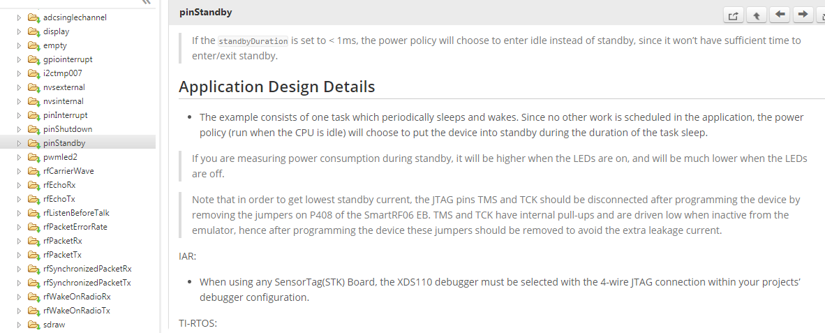
    and In example code mentioned that,please see below picture of example code.

    so from the below image and whatever result that i got , is it right call the sleep () when we want go into standby mode.please correct me. 

  • 380mA is way too much. There must be current leakage from your IO pins.
  • 380 mA indicate a hardware error, it could even be a short. Probe your board and check all impedance/ voltages.

  • Hi,
    It has been solved there is misconnection over there. Now I got 5mA current on an average of my custom board.

    Now the second problem is , if I trying to put my device into shut down mode. Using power_Shutdown() function , the device is not going into shut down State. I am using nortos mode . And I have added required .h files of power module. But still the isn't go into shutdown , current is still same as shown before.please tell me where i am getting wrong.


    Thank you
    Nilesh
  • 50ma is still too much. You should check if there’s current leakage on IO pins first.
  • Hi Nilesh,

    Do you run in debug mode when trying to enter shutdown mode? If so, that will prevent going into proper shutdown mode (debugger will block powering down). Please disconnect your debugger and try again.

    Best Regards,
    R.M
  • Hi,

    i am not using in debugger mode. i simply use the button interrupt to go into shutdown mode. my external interrupt working properly but the power_shutdown() is not working.

    Thank you
  • Hi,

    Does your code run OK on a CC1310 LP? Does it enters shutdown then? Can you share your code?

    Best Regards,
    R.M
  • Hi,

    My code in run on CC1350 LP, i have that LP.

    here i am sharing my code below.


    PIN_Config buttonForShutdown[] = {
    Board_PIN_BUTTON1 | PIN_INPUT_EN | PIN_PULLUP | PIN_IRQ_NEGEDGE | PINCC26XX_WAKEUP_NEGEDGE ,
    PIN_TERMINATE /* Terminate list */

    };


    void buttonCallbackFxn(PIN_Handle handle, PIN_Id pinId)
    {
    PowerCtrlPadSleepEnable();
    int_fast16_t status;
    CPUdelay(8000*50);
    if (!PIN_getInputValue(pinId))
    {
    /* Toggle LED based on the button pressed */
    switch (pinId)
    {
    case Board_PIN_BUTTON1:
    status = Power_shutdown(0,0);
    break;

    default:
    /* Do nothing */
    break;
    }
    }
    }

    void DT_GetandWakeFromShutdown(void)
    {

    uint32_t rSrc = SysCtrlResetSourceGet();

    buttonPinHandle1 = PIN_open(&buttonPinState, buttonForShutdown);

    if (!buttonPinHandle1)
    {
    /* Error initializing button pins */
    while (1);
    }

    /* Configure DIO for wake up from shutdown */
    PINCC26XX_setWakeup (buttonForShutdown);

    /* Setup callback for button pins*/
    if (PIN_registerIntCb(buttonPinHandle1, &buttonCallbackFxn) != 0)
    {
    /* Error registering button callback function */
    while (1);
    }

    }

    please check it once , where i am getting wrong

    Thank you
  • Hi,

    As you said I have send the code 3 days ago ,still I haven't get the reply yet. I still stuck at this point and I have solve it immediately..

    Because as per my assumption I thought the standby mode function will work properly . And I get lowest current consumption in standby mode . But your standby mode example code is not working..if you have doubt you can check what is current when it goes into standby mode.

    And because of that I shifted over shutdown mode. But still I facing problem in shutdown mode.so please reply m as soon as possible..

    Thank you

    Nilesh

  • Do you try pinShutdown example at dev.ti.com/.../ ?
  • Hi,

    Yes i have tried pin shutdown example code. and it is working but it's given in rtos , and i don't know RTOS .
    if you have any pin shutdown code without rtos then share me.


    Thank You
    Nilesh
  • Hi Nilesh,

    What is your wanted behavior with the code that you provided?
    It looks like you configure and use the same pin both for entering shut_down and wake-up from shut_down (both on neg edge)?

    When you measure the current in shut_down, do you remove the UART and JTAG headers on your Launchpad (RxD, TxD, TMS & TCK)?

    Best Regards,
    R.M
  • Hi,
    Yes I have configured it for get into shutdown and Wake Up from the shutdown. but it is not working .
    just tell me how i configure the power shutdown mode. Please explain me why your Standby mode is not working using sleep function


    Thank You
  •   Hi,

    i have just checked your example code pin standby with your development board. i flash the code into LP and after flashing i removed the all the Debugger connector and Disconnect the power supply and Gives  the 3.3 volt directly to the controller.

    i have set the standby mode time 10 sec to stay in standby mode. in that mode i am getting 1.6 microA current .

    and same code i am running in our custom board . i am getting 9 microA current in standby mode. so i am not getting this how this big difference is happen. here i am same giving the 3.3 v directly to the battery.

    please tell me is there any hardware /Software issue. if yes then please explain me.

    Here i am attaching screenshot below  

  • Dear Nilesh,

    Sounds like a HW issue but difficult to say without knowing your custom board.
    Can you post the schematic and layout of your custom board?

    Best Regards,
    R.M
  • Hello Sir,
    I have solved the issue. it's hardware issue ,some of the components consume more current. right now i removed that components.
    after checking the current consumption ,now i am getting 2.1 microA current in sleep mode function.

    Because this sleep Mode function i am going to use to reduce my battery power consumption when i am not sending data. so just ensure from you that it is safe to use that sleep function to increase my battery life.

    As mentioned sleep function is nothing but standby mode. and standby mode is also better to use my application. consuming 0.6 microA current when it is in sleep mode.

    please tell me about this ,bcoz i think it's better for the battery life.


    Thank You
    Nilesh
  • Hi Nilesh,

    Good that you where able to resolve the HW issue.

    Sleep puts your device into standby mode and since you are getting around 2uA you are in standby mode.
    What is the accuracy and resolution on the instrument you are using to measure the current?

    Best Regards,
    R.M
  • Hello Sir,
    As per the Manual the accuracy of a device is 0.09%.

    Thank You
    Nilesh Dalvi
  • Hi Nilesh ,

    You will probably not be able to accurately measure standby current with a multimeter. Do you have a DC Power Analyzer?

    I recommend that you take a look at this app note: www.ti.com/.../swra478

    Best Regards,
    R.M