This thread has been locked.

If you have a related question, please click the "Ask a related question" button in the top right corner. The newly created question will be automatically linked to this question.

CC1310EMK: CC13XXEM-7XD-7793_4L current issue

Part Number: CC1310EMK

Hi everyone,

I am currently evaluating the CC13xxEM-7XD-7793 for current consumption.  I am using

the SmartFR06 Evaluation Board PCB v1.2 and using the designated VDD to EM as instructed

to measure current in the SmartRF06 Evaluation Board PDF (Figure 24 Measuring Current Consumption Using Jumper J503).

I followed the User Guide and have removed the recommended jumpers to isolate the SmartRF06 EV from the CC13XX EVB.

Here are my readings and would like someone from TI's to verify my findings or let me know otherwise:

Using the USB as a Power Source

Awake Current Consumption:  6.56mA for approx. 1minute

Sleep Current Consumption: 81uA for approx. 1minute

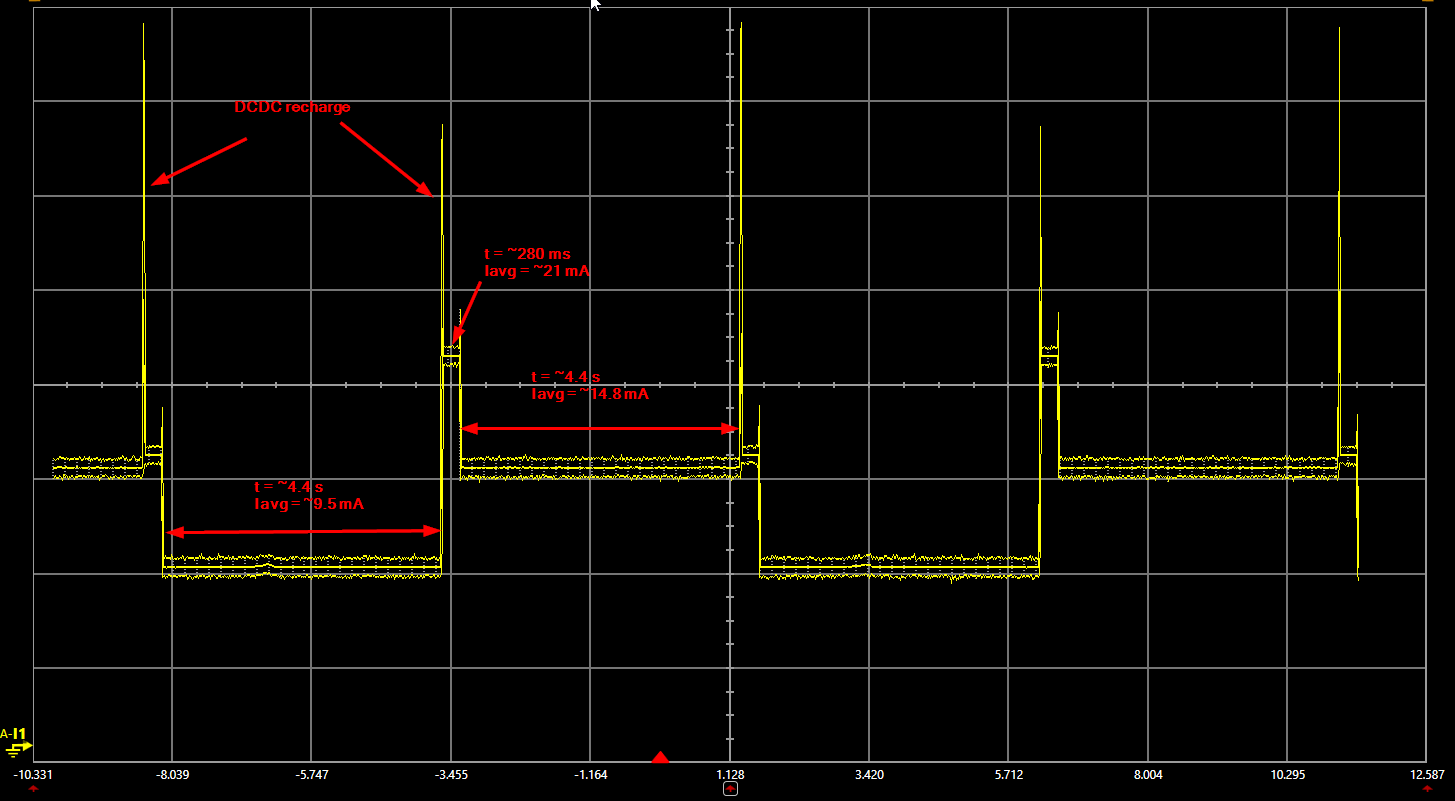
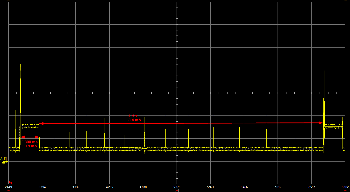
During Sleep short burst: 5.7mA approx. 300ms in duration


Using the AAA battery as a power source:

Awake Current Consumption: 11.4mA for approx. 1minute

Sleep Current Consumption: 4uA for approx. 1minute

During Sleep short burst: 4.5mA approx. 300ms in duration

I also found that sometimes on power up the unit will come up

in the sleep cycle and sometimes it comes up in the wake cycle.

This assumption is based on viewing the current readings, because

there is no viewing aid on the CC13xxEM board.

Thank you in advance.

  • Which SW example do you test this?
  • Hi Neil,

    What instrument are you using to measure the current consumption? A multimeter or a DC power analyzer? Note that CC1310, when in standby, the DCDC converter will go into recharge mode, meaning that you will see current spikes which will be hard to measure on a multimeter.

    Also, when you say awake, is the RF core in TX or RX? Or are you only using the Cortex M3?

    Please refer to the datasheet for details on what current consumption you can expect in the different modes.

    -Simon
  • Hi everyone,

    I am including a capture of the actual pulses seen while the module is in the sleep

    cycle.  There are 12 of these pulses during the 1 minute sleep cycle.

  • Hi YK Chen,

    Here is the SW that was sent to me by Andres Blanco (LPRF Applications Engineer).

    Here is the OneDrive shared link:

  • Hi Simon,

    I used a HP 3478A multimeter and an oscilloscope to capture the pulses.

    "Also, when you say awake, is the RF core in TX or RX? Or are you only using the Cortex M3?"
    I am using what I described above the two EVM boards.

    "Note that CC1310, when in standby, the DCDC converter will go into recharge mode, meaning that you will see current spikes which will be hard to measure on a multimeter. "
    You can look at the oscilloscope wave form which I captured.

    Andres Blanco (LPRF Applications Engineer) from ti, said the following: These recharge pulses can go up to 6mA and only last ~50us.
    You can see what I captured above.

  • Hi Neil,

    It's not clear to me what you mean by awake. If the MCU is awake running at 48 MHz, 2.5 mA is expected, but you also have to add on the current consumption of the peripherals you are using. Without knowing that I can't say if the current consumption is as expected or not.

    The expected sleep current (or standby as we call it in the datasheet) is 0.7 uA with the RTC running + RAM and CPU retention. In this mode you should see the recharge pulses. Figure 45 in this application report shows how recharge pulses should look like: www.ti.com/.../swra478d.pdf

    -Simon
  • Hi Simon,

    Since you work for TI you should have access to the SmartRF06 Evaluation Board and the CC13xxEM board. If you download the software (I uploaded above)and program the CC13xxEM board you should have an equivalent unit to what I have. This will make things easier for you to understand/work with and you don't need to rely on information from my end that might cause confusion. Once you have all of this, use the VDD to EM available on the SmartRF06 to take current readings. Once you have done this, you can confirm if what I am seeing is the same as what your seeing at your end.

    When your getting your current readings, try the USB as a power source and also try the AAA battery as a source, just to see the different current readings.

    Thanks,
    Neil
  • Neil,

    Can you upload the .zip-file directly to E2E (attach it to a post) as I am not able to download files from 3rd party files sharing sites.

    Thanks,
    SImon
  • HI Simon,

    I tried this morning to upload the .zip file directly, unfortunately it exceeds the max size allowed. Can you ask Andres Blanco (LPRF Applications Engineer) to send this to you internally?

    Regards,
    Neil
  • Hi Simon,

    Let me try the following:

    cc1310lp_Feb_4_2019 (2).zip

  • Hi Neil,

    This is the measurement results I got from you code. Since you haven't explained what your code is doing, I'm not able to help you any further. 

  • Hi Simon,

    The code that I sent you is not my code. This code was sent to me by Andres Blanco (LPRF Application Engineer) TI. I am simply evaluating at this point the current consumption of the device (CC13XXEM board). You can ask Andres Blanco exactly what this code is doing and help me understand as well with a reply in this forum ( please separate the explanation from the current measurement issue).

    After reviewing the pdf you linked, it appears that the pulses we are seen of 300ms are the TX pulses explained in that pdf. In that pdf, the TX pulses are approx. 100ms.

    Originally on the oscilloscope capture I posted, I called them the charge pulses, which I know now that was incorrect.

    As for your capture, I don't understand why the 4.4s sleep periods don't always end up at the same level?
    The Iavg of 21mA (280ms pulse) seems pretty high, we are getting 11.4mA?
    Your sleep current also seems pretty high, I don't understand why? According to Andres, this period should be around 70nA.

    Let me know what you think?

    Thanks,
    Neil
  • Hi Neil,

    For current consumption evaluation I recommend to use the pinStandby example: http://dev.ti.com/tirex/#/?link=Software%2FSimpleLink%20CC13x0%20SDK%2FExamples%2FDevelopment%20Tools%2FCC1310%20LaunchPad%2FTI%20Drivers%2FpinStandby%2FTI-RTOS%2FCCS%20Compiler%2FpinStandby 

    It looks like you have done testing without any leds. Here is a new test without the leds:

    This is more comparable to what you have measured. 

    -Simon

  • Hi Simon,

    I see that this pinStandby example resembles what we are seeing, but what I don't understand is why are you analyzing
    an example of something other than what TI sent us for evaluating?

    Have you contacted Andres Blanco to explain what the code is doing during the pulses? I would like an explanation of what is happening
    with the code he sent us.

    Thanks,
    Neil
  • Hi Neil,

    The screenshot I posted above is from the code you sent me. I have not posted any screenshots of the pinStandby example. However, I'll recommend to use the pinStandby example if you want to evaluate low power consumption.

    -Simon
  • Hi Simon,

    Ok, I miss understood the previous post. Please contact Andres Blanco, so that he can explain what is happening in the 300ms pulses, also
    what is the unit doing for 1 minute while it is up?

    Regards,
    Neil
  • Hi Neil,

    You SW is running the TI15.4 stack switching between collector and sensor. It switches every 60 seconds if it doesn't find a collector (in sensor mode) or sensors nearby (in collector mode).

    Form the measurements it looks like the device is in collector mode and not going to sleep; every 4.4s is a beacon being sent out and then staying in RX mode for 300 ms.

    -Simon