This thread has been locked.

If you have a related question, please click the "Ask a related question" button in the top right corner. The newly created question will be automatically linked to this question.

RTOS/CC1310: CC1310 sleep problems

Part Number: CC1310
Other Parts Discussed in Thread: CC2650

Tool/software: TI-RTOS

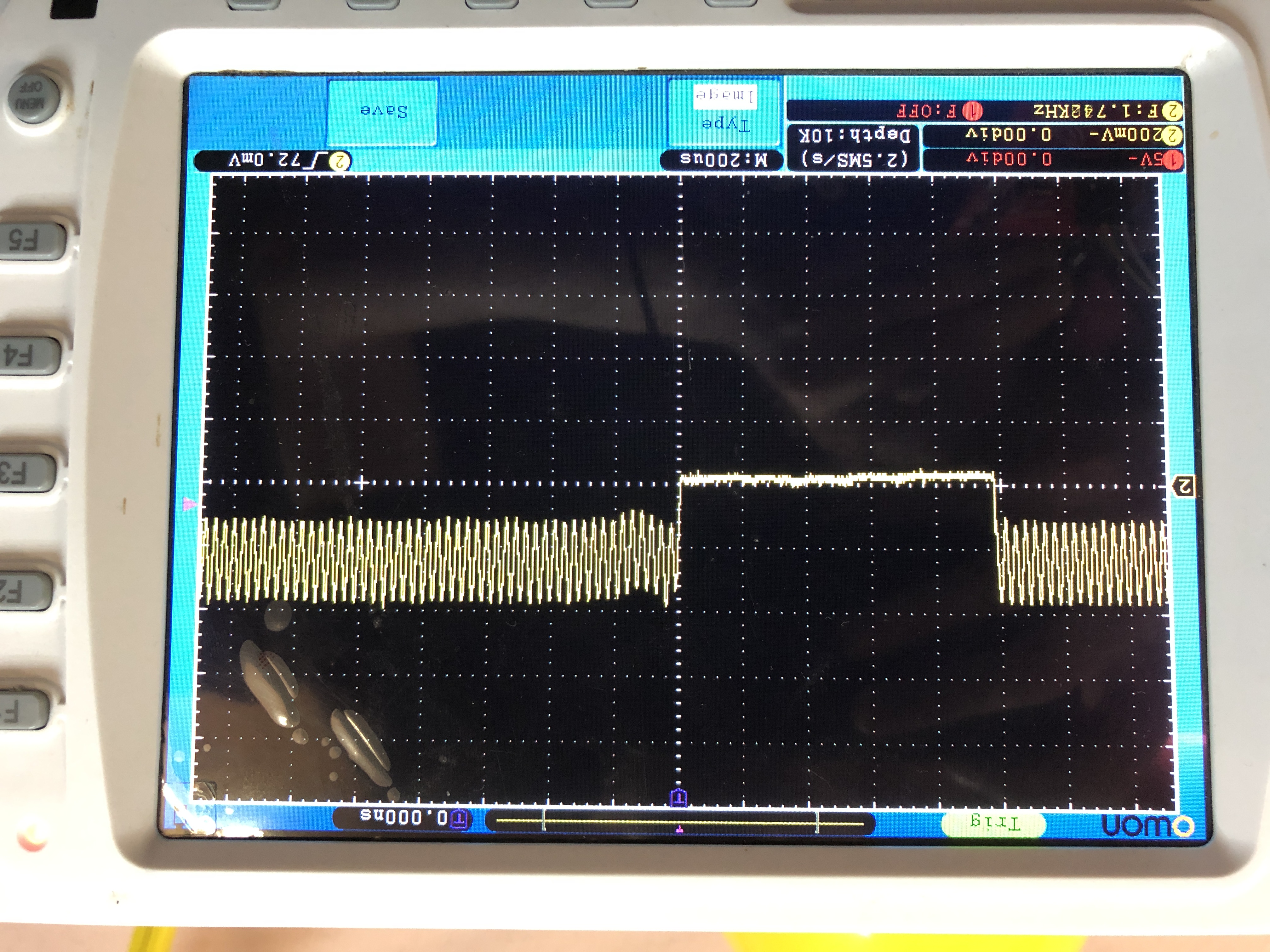
Hey. I am developing my board with cc1310 (4x4 rev 2.1). I can't go to standby mode with low power consumption. I use the pinstandby example, and it works (I see this by debugging code). When creating the board, I used the reference board design from the TI website. Also on the board are the same crystals as on the CC1310 LaunchPad board. And I see a sine wave on a crystal of 32 kHz. The board itself works well - spi, rf and so on works. In addition to the cc 1310 on the board is now nothing. In the pinstandby example in the CC1310_LAUNCHXL .h file, I specified PIN_UNASSIGNED on those contacts that are not in this version of the chip (I also tried to specify PIN_UNASSIGNED for each contact). As a result, I always see 3-4 mA in sleep mode. I tried calling the OSCHF_DebugGetExpectedAverageCrystalAmplitude () function, which returns 465. But if you call the OSCHF_DebugGetCrystalAmplitude() function, it will return 0. But if you call OSCHF_TurnOnXosc() before calling these functions, then OSCHF_DebugGetCrystalAmplitude() will return 420. I tried many solutions to this problem with various issues on this forum, but nothing helps. Can you tell in which direction to go?

P.S.

Sorry for my English!

  • The 24 MHz xtal is only on when the radio is on. When only the CM3 is running the internal HSOSC is used.

    Could you confirm that the debugger is not connected when running this example since it's not possible to go to standby with the debugger connected.
  • If by disabling the debugger you understand the disconnection of the wires between the board and the programmer, then yes, this is done. The debugger is disabled. If this is not the case, could you explain what the debugger is turning off? I also noticed that if I use an internal crystal at 32 kHz instead of an external one (I fixed this in the ccfg.c file), then I see 2.2 mA instead of 3.5 mA. Could it say that there is still a problem with an external 32 kHz crystal?
  • And how do you measure the current? I assume you don't have any LEDs that draw current?

    You write " I use the pinstandby example, and it works (I see this by debugging code)", could you elaborate how you see that it works?
  • I use a laboratory power supply and measure the current with a multimeter. Yes, no LEDs. When I start debugging code in CCS, I can step by step to the moment where the sleep () function is called, therefore I believe that the board is initialized correctly. I also ran other examples (rfPacketTx, empty spi programming (I see clk on the oscilloscope and transmitted data)), and everything works fine. I also tried to remove the initialization of the LEDs from the pinstandby example, but this did not help, as did the initialization of all GPIO values ​​of 0 (with different settings (pulldown / pullup)).
  • Is it possible to take a look at the schematic for your board and the board file you are using? I don't see why you are not able to get the sleep current based on what is described above.
  • What is crossed out in the diagram is now absent on the board. In general, when creating the board, I was guided by the reference design from the TI website.

  • Not related to the SLEEP issue but curious:
    - What is the thought behind the antenna solution?
    - Note that CC1310 has build-in load caps for the xtal. If you want to use external ones you need to turn of the internal ones. See www.ti.com/.../swra640
    -----
    Sleep:
    - Do you have a voltage difference between VDDS1 and VDDS2? Why have you selected to separate the VDDS lines, I believe we don't use this in our reference design.
    - Are the devices you have marked with X not mounted?
    - The current consumption you give is "strange" in the respect that the CC1310 is normally don't draw 3 - 4 mA in any state (check the datasheet) . This indicate that you include something else in the measurement.
  • The board is fpga, with which the source signal from cc1310 is expanded.
    Caps for xtal are not installed on the board (the seats are left just in case).

    No, there is no difference between VDDS1 and VDDS2. Since the board is used with two layers, it is not possible to combine the power of a single landfill, so the division into two parts was done, which (if you look at the board's scheme) as a whole is one common food ground (shared only at the places of inductances). We tried to remove one of the inductances and connect these two power sections (VDDS1 and VDDS2) with a small wiring to make it as on the reference board, but this did not help. Earlier, I said that when using internal crystal at 32 kHz, the current consumption is at the level of 2 mA. Now I have found that such a current remains even when using an external crystal (provided that the example of the pinstandby project is used, in the settings of which those contacts that are not present are set to PIN_UNASSIGNED).

    Yes, devices marked with x are not installed. Now on the board, except cc1310, crystals and components for power supply (capacitors, resistors and inductances), nothing is installed. The board was also measured using a multimeter for the presence of any contact closure. But no such closures were detected.
  • Now I have done the following:

    1. I used the PinStandby example from “Resource Explorer” -> “Software” -> “TI-RTOS for CC2650” -> “Development Tools” -> “CC1310 Launchpad” -> “Driver Examples” in CCS.

    2. After that, I put unused pins in the file CC1310_LAUNCHXL.h in PIN_UNASSIGNED. Now I see a current of 2.2 mA.

    3. I replaced the board files in this example taken from
    C: \ ti \ tirtos_cc13xx_cc26xx_2_21_00_06 \ products \ tidrivers_cc13xx_cc26xx_2_21_00_04 \ packages \ ti \ bo ards \ CC1310DK_4XD. I also see 2.2 mA. This is already less than 3-4 mA, but still not that. With this, I repeat that the board removed all unnecessary components, except cc1310. And when measuring current, the jtag debugger is disabled.
  • I found a very strange thing that I can not explain. We bought several sets of cc1310 4x4 chip. As it turned out, they differ a little on the markings on the case - there is a chip with the marking CC1310F128 TI 78J P6CJ G4, and there is with the marking CC1310F128 TI 751 ANPL G4. So now turn to datasheet. It follows from it that 11 contact is responsible for power supply, and 20 is connected to ground. And the strange thing is that if on the chip with the label ANPL G4 at the end, check these contacts with a multimeter for a circuit, that is, to perform a dial for the board, then we just see the circuit. But if you check the same thing on a chip labeled P6CJ G4 at the end, then there is no such thing, and it corresponds to the datasheet. These measurements were carried out on an absolutely bare chip. How can you explain this?
  • Could you clarify some:
    Does that mean you measure the impedance between pin 11 and pin 20 and the impedance is different between the two versions of the chip?

    Do you see different behavior running the same code in the two different versions?

    Here I mean version as in different marking
  • Yes, we measure the DC impedance between pins 11 and 20, and in different versions of the chip it is different. We will test the code on a different version of the chip a bit later, as we will replace the chip. After that, I write you what we got.
  • What was the impedance you measured?
  • To make it clear what we are measuring, I attached a photo of a multimeter, which shows in which mode it is located. In one case, we see 1., and in the other 0.020 (while the multimeter emits a signal, indicating the closure of these contacts).

  • Not a very big difference, try with the 200 ohm setting just to be sure.
  • With a setting of 200 ohms, the multimeter shows 30.0. And on another chip, even when setting up 200M, it shows 1. (as in the photo above).
  • Just to verify: Are these chips soldered on to a board or are you measuring directly on a chip not connected to anything?

    Have you been able to check if the code examples are running in the same manner on both versions?
  • We measure on a chip that is not connected to anything. We checked two different versions of this chip (with different markings), and on the chip where there is no closure, the code works fine. We see a dream (only the value of the current ranges from 10 to 100 µA, but we assume that this is due to the fact that the I / O pins are in the floating state, and perhaps you can tell us how to fix this). We also tried to call the Power_shutdown (0,0) command, and we saw 0 μA, which indicates the correct operation of the chip. We cannot explain why there is a closure problem on certain chips. Perhaps this is just a mistake of production.

    Tomorrow we will fully test our device, with all the components on the board, and then we can say for sure that the problem was the malfunction of the chip.
  • Ok, let me know the result of the testing.
  • We tested our device with all the components on the board. Everything works as expected. Only we still have trouble sleeping. It lies in the fact that we see 80 μA in a dream (in two versions: when the board has only cc1310 and when the board has all the components). If we try to call Power_shutdown (0,0) at a certain point, then we see no more than 1 µA. We tried various combinations with examples (different initialization of pins, use of projects for TI / RTOS or examples of projects for LAUNCHPad cc1310), but the result is the same. In this case, if we indicate in the code to use an internal crystal at 32 kHz, then the current becomes a bit lower. Maybe you have ideas on how to fix this? Because at the moment our problem is not fully resolved.
  • - As I understand it you see the same standby current on a board with only CC1310 and with all the components mounted? (80 uA)
    - Could you confirm that you say this using pinstandby example?
    - Did you see any difference using chips with different lot code (marking)?
    - I previously asked for your board file, I got the layout but I need the file(s) where you have mapped the DIOs. It sounds like one or more pins are floating or similar causing leakage currents.
  • Answers to your two questions:
    Yes - (As I understand it you see the same standby current on a board with only CC1310 and with all the components mounted? (80 uA))
    Yes - (Could you confirm that you say this using pinstandby example? )

    Yes, we see changes for different markings. The chip labeled CC1310F128 TI 751 ANPL G4 shows 3-4 mA in sleep mode, while the chip labeled CC1310F128 TI 78J P6CJ G4 shows 80 µA with the same code. On board account file. Do you want to see the Board.h file?
  • Yes, plus your version of CC1310_LAUNCHXL.h
  • 6177.CC1310_LAUNCHXL.h

    I tried to set all contacts to PIN_UNASSIGNED

  • I apologize. Forgot to attach this file in the past message.

    8741.Board.h

  • Are you able to measure the current draw with a different instrument? I'm not sure if the rechange pulses are handled equal in all multimeters (most of the time the multimeter do an average. (see chapter 2 in www.ti.com/.../swra478d.pdf for recharge pulses)

    Do you have a launchpad you can do a reference measurement on?
  • Yes, we tried to measure with another multimeter and a laboratory power supply that shows current consumption. The result is the same everywhere. We also have a launchpad, and its performance is normal (8-10 µA, this is probably due to the flash drive installed on this board).

    But we are faced with another problem, which is possible and sleep well. It consists in the following:
    If we take the pinstandby project for the CC1310 LaunchPad, and change it for a 4x4 chip (in the CC1310_LAUNCHXL.h file, we set unused contacts to PIN_UNASSIGNED). After that we remove the LEDs from on and off from the main code, and instead we switch the legs (for example, IOID_9), while the dream remains (the sleep function), we see the following situation - If we select XOSC or RCOSC as the LF clock in the ccfg.h file, we see the IOID_9 contact jump, but if we select "LF clock derived from High Frequency XOSC" as the clock, then everything works as expected. I can understand that XOSC may not work due to a faulty external crystal, but that’s why the program doesn’t work with RCOSC, is it an internal crystal? We soldered the external crystal at 32 kHz, but this did not solve the problem and RCOSC did not work. How can this behavior be explained? The same code was tested on other examples from CCS (TI / RTOS examples) - the result is the same. Although we do not see the switching of the contact, the chip still goes to sleep with a consumption of 100 μA, but this is not the ideal behavior.

    I would also like to clarify that on the oscilloscope when using XOSC we see a sine wave, exactly the same as on the CC1310 Launchpad. Just in case, I attach the main code in which we made the above changes.

    #include <unistd.h>
    
    /* Driver Header files */
    #include <ti/drivers/PIN.h>
    #include <ti/drivers/pin/PINCC26XX.h>
    
    /* Example/Board Header files */
    #include "Board.h"
    
    /* Led pin table */
    PIN_Config LedPinTable[] =
    {
        IOID_9    | PIN_GPIO_OUTPUT_EN | PIN_GPIO_LOW | PIN_PUSHPULL | PIN_DRVSTR_MAX,
        PIN_TERMINATE
    };
    
    void *mainThread(void *arg0)
    {
        PIN_State   pinState;
        PIN_Handle  hPin;
        uint32_t    standbyDuration = 5;
        uint32_t currVal = 0;
    
        /* Allocate LED pins */
        hPin = PIN_open(&pinState, LedPinTable);
    
        /*
         * Repeatedly sleeps for a duration, to allow repeated entry/exit
         * from standby. The LED states are toggled on each iteration
         */
        while(1) {
            /* Sleep, to let the power policy transition the device to standby */
            sleep(standbyDuration);
            currVal =  PIN_getOutputValue(IOID_9);
            PIN_setOutputValue(hPin, IOID_9, !currVal);
        }
    }

  • I clarify that by XOSC I mean LF XOSC
  • A couple of questions: what do you mean by "the dream remains"? You have used the word dream also before and not sure what you mean.

    Are you able to comment on the estimated sale volume for this product?

  • "the dream remains" - I mean sleep (sleep remains). Sorry for my incorrect English. Approximate sales for the first year are approximately 1000-1500
  • Back to my problem. Below I attached a picture. It shows the sine wave from crystal at 32 kHz. An empty gap (hole, pit, and so on) appears as soon as I try to call the Task_sleep () function. If in the code written above (in the previous message) to comment out the call to this function, then the sine wave goes without interruption. Apparently, due to this gap, the chip cannot go to sleep and therefore I see a strange program execution (the IOID_9 leg does not switch every 5 seconds). This behavior occurs when using an internal LF crystal (LF RCOSC), and when using an external (LF XOSC). I replace the crystal in the ccfg.h file (#ifndef SET_CCFG_MODE_CONF_SCLK_LF_OPTION)

  • If you have selected the internal RCOSC as LF clock you should not have a signal on the XOSC pins in the first place.

    I suspect that it's something wrong with your hardware but I'm not able to see what it is based in the information given.
  • At the moment, we ourselves can not understand the cause of this problem. Therefore, we decided to create a new version of the board using cc1310 5x5. It will take about two weeks. If you can, please do not close this topic. When the new version of the board is ready, we will inform you about the results. Thank you for helping us with this issue.
  • I will press "TI thinks resolved" to avoid having this thread open in the system while you are spinning the board but the ticket will automatically reopen when you post something new in this thread.