This thread has been locked.

If you have a related question, please click the "Ask a related question" button in the top right corner. The newly created question will be automatically linked to this question.

RTOS/CC1352P: how to select between RF_P_SUB_1GHZ and TX_20DBM RF paths on CC1352P

Part Number: CC1352P
Other Parts Discussed in Thread: CC1352R

Tool/software: TI-RTOS

Greetings,

I've got 2 CC1352R1 Launchpads (CC1352R1 Rev C) that I've been able to easily TX/RX between using the rfEasyLinkNp example (simplelink_cc13x2_sdk_2_30_00_45/examples/rtos/CC1352P_4_LAUNCHXL/easylink/rfEasyLinkNp).

I now have a custom board design with a CC1352P Rev C which only uses the TX_20DBM RF path that I am trying to get to TX/RX to one of these CC1352R1 Lauchpads and have not seen any TX/RX activity pass. I'm thinking its likely because the rfEasyLinkNp example is configuring the chip to use the RF_P_SUB_1GHZ and my custom board is using the TX_20DBM RF path... how do I configure this?


Thanks,

Tim

  • Please take a look at the rfDriverCallback function in the CC1352P_4_LAUNCHXL_fxns.c or CC1352P_2_LAUNCHXL_fxns.c

    BR
    Siri
  • I understand how the rfDriverCallback manipulates the GPIO's connected to the mux but what is it that configures the modes in the first place?

    How do I configure rfEasyLinkNp to use TX_20DBM?

    How do I configure rfEasyLinkNP to use 2.4GHz?

    If its a matter of using the AT API to set specific values please provide examples as I've been unable to get any of the ATPFR frequencies to work accept for 433.92Mhz which appears to be the default. Here is an example session:

    EasyLink-v2.40.02
    AT+I 1
    OK
    ATPPW?
    12
    OK
    ATPFR?
    433920318
    OK
    ATPFR=433920318
    OK
    ATPFR=868000000
    Error 0005
    ^^^ TX Error???

    Also I'm not able to print debugging details from within rfDriverCallback using the AtTerm_* functions from AtTerm.h which is making it really difficult to debug. It seems as if the app crashes after displaying a message or two... Is there something funny about the context that rfDriverCallback is called in? Note I'm doing this on my custom board which only has the UART interface back to the SoC for debug communication.

    using CC1352P revC, simplelink_cc13x2_sdk_2_30_00_45, and ccs 7.4.0.00015's GCC compiler

    Thanks,

    Tim

  • The rfDriverCallback manipulates the GPIOs and it does that based on the current PA configuration (using RF_getTxPower(client).paType) and
    by checking what setup command you are using and what the loDivider is set to.

    Basically that means that if you do a code export from SmartRF Studio and export settings for +20 dBm PA, these settings will give the driver enough information set the GPIOs correctly.
    Siri
  • Ok, I see now how the RF Core settings are very specific to the mode you want to use. SmartRF Studio creates smartrf_settings.c and smartrf_settings.h. What is the simplest 'example' app that I can plug those files into?

    Alternatively is there just a couple of settings you can point me to that will use the TX_20DBM output rather than the RF_P_SUB_1GHZ? I'm finding that all the examples in the SDK are typically way more than I need to prove my hardware can TX and RX packets.

  • I would recommend you to take the rfPacketTX example, and then try it with settings exported from SmartRF Studio. Export settings both with the 20 dB PA enabled and disabled.

    BR
    Siri
  • By diffing a SmartFR studio (version 2.12.1) code export for the high gain PA enabled vs disabled I see only the following differences:

    $ diff 13dbm_packet_RX/smartrf_settings.c 20dbm_packet_RX/smartrf_settings.c
    27,28c27,28
    < // TX Power: 13.5 dBm (requires define CCFG_FORCE_VDDR_HH = 1 in ccfg.c, see CC13xx/CC26xx Technical Reference Manual)
    < // Enable high output power PA: false
    ---
    > // TX Power: 20 dBm (requires define CCFG_FORCE_VDDR_HH = 0 in ccfg.c, see CC13xx/CC26xx Technical Reference Manual)
    > // Enable high output power PA: true
    105,108c105,106
    < // DC/DC regulator: In Tx with 14 dBm PA setting, use DCDCCTL5[3:0]=0xF (DITHER_EN=1 and IPEAK=7). In Rx, use DCDCCTL5[3:0]=0xC (DITHER_EN=1 and IPEAK=4).
    < (uint32_t)0xFFFC08C3,
    < // Tx: Set PA trim to max to maximize its output power (in ADI0, set PACTL0=0xF8)
    < ADI_REG_OVERRIDE(0,12,0xF8),
    ---
    > // DC/DC regulator: In Tx, use DCDCCTL5[3:0]=0xC (DITHER_EN=1 and IPEAK=4). In Rx, use DCDCCTL5[3:0]=0xC (DITHER_EN=1 and IPEAK=4).
    > (uint32_t)0xFCFC08C3,
    173c171
    < .txPower = 0x013F,
    ---
    > .txPower = 0xFFFF,

    These differences along with a couple others already exist in smartrf_settings.c based on USE_SUB1_HIGH_PA_SETTING and CCFG_FORCE_VDDR_HH:

    pOverrides:
    #if (CCFG_FORCE_VDDR_HH && ~USE_SUB1_HIGH_PA_SETTING)
    // TX power override
    // DC/DC regulator: In Tx with 14 dBm PA setting, use DCDCCTL5[3:0]=0xF (DITHER_EN=1 and IPEAK=7). In Rx, use DCDCCTL5[3:0]=0xC (DITHER_EN=1 and IPEAK=4).
    (uint32_t)0xFFFC08C3,
    // Tx: Set PA trim to max to maximize its output power (in ADI0, set PACTL0=0xF8)
    ADI_REG_OVERRIDE(0,12,0xF8),
    #else
    // DC/DC regulator: In Tx, use DCDCCTL5[3:0]=0xC (DITHER_EN=1 and IPEAK=4). In Rx, use DCDCCTL5[3:0]=0xC (DITHER_EN=1 and IPEAK=4).
    (uint32_t)0xFCFC08C3,
    #endif
    #if (USE_SUB1_HIGH_PA_SETTING)
    // override_phy_tx_pa_ramp_genfsk_hpa.xml
    // Tx: Configure PA ramping, set wait time before turning off (0x2F ticks of 16/24 us = 31.3 us).
    HW_REG_OVERRIDE(0x6028,0x002F),
    // txHighPA=0x0020AA1B
    (uint32_t)0x82A86C2B,
    #endif
    (uint32_t)0xFFFFFFFF,

    rfc_CMD_PROP_RADIO_DIV_SETUP_PA_t RF_cmdPropRadioDivSetup:

    #if (USE_SUB1_HIGH_PA_SETTING)
    .txPower = 0xFFFF,
    .pRegOverride = pOverrides,
    .centerFreq = 0x01EA,
    #else
    .txPower = 0x013F,
    .pRegOverride = pOverrides,
    .centerFreq = 0x01B1,
    #endif

    rfc_CMD_FS_t RF_cmds:

    #if (USE_SUB1_HIGH_PA_SETTING)
    .frequency = 0x01EA,
    .fractFreq = 0x0000,
    #else
    .frequency = 0x01B1,
    .fractFreq = 0xEB9A,
    #endif

    The README.html in rfPacketRx says to set USE_SUB1_HIGH_PA_SETTING=1 to enable it the high gain PA. The high gain PA refers to the 20DBM RF path correct? That #define is only used within smartrf_settings.c and nowhere else within the rtos/kernel right?

    I'm confused on what CCFG_FORCE_VDDR_HH is and how it relates to this. CCFG_FORCE_VDDR_HH is used in smartrf_settings.c as well as files included in ccfg.c. SmartRF Studio has a comment that says for the 20dBM path you need to set CCFG_FORCE_VDDR_HH=0.

    If I add -DUSE_SUB1_HIGH_PA_SETTING=1 in my makefile  I do see that rfDriverCallback shows sub1GHz=true and paType=RF_TxPowerTable_HighPA which should indicate TX/RX is via 20DBM RF path (finally!) but I get no packets received (with CCFG_FORCE_VDDR_HH=0 or CCFG_FORCE_VDDR_HH=1)

    Should the CC1352P Rev C chip we have on our board work with the CC1352P_4_LAUNCHXL configuration or are their other changes that would need to be made to the examples? Our board has the CC1352P hooked up the same way as on the CC1352P_4_LAUNCHXL except the antennaPins are unconnected and we don't have an RF Mux.

    Does the CC1352P_4_LAUNCHXL work with rfPacketTx/rfPacketRx out the 20DBm path with simplelink_cc13x2_sdk_2_30_00_45 with USE_SUB1_HIGH_PA_SETTING=1?  I dont' have a pair of CC1352P_4_LAUNCHXL to test with (I have a pair of CC1352R1_LAUNCHXL which doesn't have the 20DBm path)

  • High gain PA refers to the 20 dBm PA

    The ccfg.c file you can find here:

    C:\ti\simplelink_cc13x2_sdk_2_30_00_45\source\ti\devices\cc13x2_cc26x2_v1\startup_files

    If you modify anything in this file it will be valid for all your project using the same instance of the SDK. If you only want to change the setting for one of your projects, you should add the following to the ccfg.c file you have locally:

    #ifndef CCFG_FORCE_VDDR_HH
    #define CCFG_FORCE_VDDR_HH        0x0        // Use default VDDR trim
    //#define CCFG_FORCE_VDDR_HH        0x1        // Force VDDR voltage to the factory HH setting (FCFG1..VDDR_TRIM_HH)
    #endif

    I do not have any CC1352P_LP so I cannot test this, but I have not heard anything about the example not working as expected when using the 20 dbm PA settings.

    When it comes to what changes you need to do if your design is different from the LP, I need to get a HW person commenting on.

     Siri


  • I'm defining CCFG_FORCE_VDDR_HH via my CFLAGS but my question is when I'm using the High gain PA (USE_SUB1_HIGH_PA_SETTING=1) should I set CCFG_FORCE_VDDR_HH to 0 or 1? I'm not clear what this setting actually does. I've seen it said that it changes the VDDR voltage but that still doesn't explain why and when to enable/disable it.

    I now am convinced I'm transmitting via the High Gain PA on the CC1352P; I'm setting USE_SUB1_HIGH_PA_SETTING=1, the rfDriverCallback now shows paType=RF_TxPowerTable_HighPA and I even verified on a scope that I see 1Hz bursts on the antenna of the board running rxPacketTx, however I'm still not seeing any packets received on another board running rfPacketRx. 

    To troubleshoot I'm wondering if I should be able to see these packets on the non PA CC1352R Launchpad I have (I don't see them... should I be able to?).

    Any ideas on how to determine if I have a TX issue or an RX issue?

    Tim

  • I've found that I've got some sort of antenna tuning issue as if I moved my antennas within inches of each other I see packets received.

    What resources can you point me to in order to tune the RF circuit (capacitors, inducters, and routing guidelines) for the 20dBM Sub 1GHz RF path?

    We followed the TX_20DBM circuit from the CC1352P1 Launchpad but do not use the RF switch thus unload the cap that goes to it. I noticed the inducters and capacitor values changed between CC1352P1 Launchpad and the CC1352P2 and then again in the CC1352P4 design (which dropped the individual local antenna connectors and only support the RF Mux.

    Tim
  • Hi Tim,

    Can you post your schematic for the 20 dBm section ?

    The "P" LaunchPads only uses switches for combining the RF ports. Other versions of the LaunchPads use diplexers but not for the "P" versions.

    Which component size are you using for your layout, 0201 or 0402 ?

    Regards,
    Richard
  • Richard,

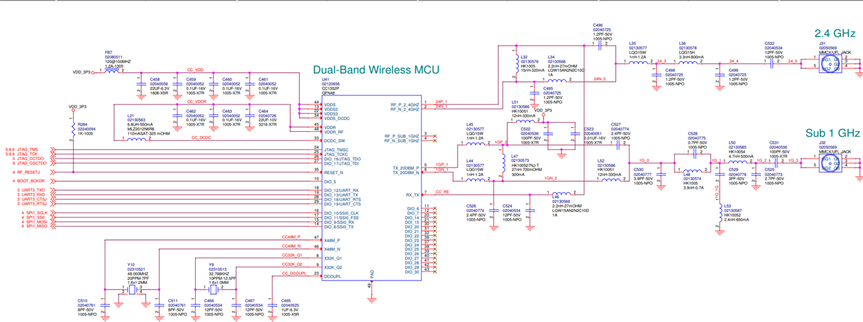
    We are using 0402 components and discrete antennas via MMXC connectors for 2.4GHz and Sub-1GHz. The antenna used is 2dBi 900-975MHz VSWR <= 2.0 Linear/vertical polarised 50ohm impedance. Here is the schematic of the CC1352P and RF path:

    Tim

  • Hi,

    With 0402 passives then I would use the component values shown below for the PA:

    Let me know which output power you measure.

    Regards,

       Richard

  • Richard,

    Where are you getting these values? Is there simulation software your using?

    Tim
  • Hi,

    It is a combination of measurements and simulations. The first stage is to perform load-pull measurements directly after the balun to determine the optimum load impedance. Once the load impedance is known, then this is entered into simulations to optimize the component values for matching/filtering.

    Regards, Richard