


Tool/software: TI-RTOS
Hello,
I am working on a project that involves transmitting GPS, accelerometer and gyroscope data from one CC1310 launchpad to another. I integrated the interfacing code (which works fine on its own) with the example. I made minor modifications to the example code as seen in the attached files.
However, the program always seems to be stuck in an infinite loop between lines 1001bbd2 and 1001bbd4 as shown in the screenshot attached. In the disassembly, the code seems to belong to the ti sys/bios part. 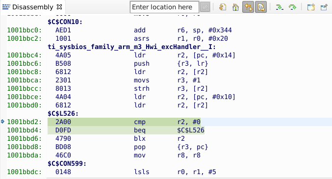
I am unable to figure it out as I have no knowledge of TI rtos. PLease help me figure it out.
/*
* Copyright (c) 2018, Texas Instruments Incorporated
* All rights reserved.
*
* Redistribution and use in source and binary forms, with or without
* modification, are permitted provided that the following conditions
* are met:
*
* * Redistributions of source code must retain the above copyright
* notice, this list of conditions and the following disclaimer.
*
* * Redistributions in binary form must reproduce the above copyright
* notice, this list of conditions and the following disclaimer in the
* documentation and/or other materials provided with the distribution.
*
* * Neither the name of Texas Instruments Incorporated nor the names of
* its contributors may be used to endorse or promote products derived
* from this software without specific prior written permission.
*
* THIS SOFTWARE IS PROVIDED BY THE COPYRIGHT HOLDERS AND CONTRIBUTORS "AS IS"
* AND ANY EXPRESS OR IMPLIED WARRANTIES, INCLUDING, BUT NOT LIMITED TO,
* THE IMPLIED WARRANTIES OF MERCHANTABILITY AND FITNESS FOR A PARTICULAR
* PURPOSE ARE DISCLAIMED. IN NO EVENT SHALL THE COPYRIGHT OWNER OR
* CONTRIBUTORS BE LIABLE FOR ANY DIRECT, INDIRECT, INCIDENTAL, SPECIAL,
* EXEMPLARY, OR CONSEQUENTIAL DAMAGES (INCLUDING, BUT NOT LIMITED TO,
* PROCUREMENT OF SUBSTITUTE GOODS OR SERVICES; LOSS OF USE, DATA, OR PROFITS;
* OR BUSINESS INTERRUPTION) HOWEVER CAUSED AND ON ANY THEORY OF LIABILITY,
* WHETHER IN CONTRACT, STRICT LIABILITY, OR TORT (INCLUDING NEGLIGENCE OR
* OTHERWISE) ARISING IN ANY WAY OUT OF THE USE OF THIS SOFTWARE,
* EVEN IF ADVISED OF THE POSSIBILITY OF SUCH DAMAGE.
*/
/*
#define _GPRMC_ 1
#define _GPGGA_ 2
#define _OTHER_ 3
#include <stdint.h>
#include <math.h>
#include <stdio.h>
#include <stdlib.h>
#include <stddef.h>
#include <unistd.h>
#include <pthread.h>
#include <string.h>
/* Driver Header files */
/*
#include <ti/drivers/GPIO.h>
#include <ti/drivers/I2C.h>
#include <ti/drivers/UART.h>
// Example/Board Header files
#include "Board.h"
#include "MPU6050.h"
//#include "sensors.h"
#define A_CONFIG 0x00
#define G_CONFIG 0x00
typedef struct
{
float accel[3];
float gyro[3];
float temp;
float lat;
float lon;
float alt;
} OutputData;
OutputData payload ;
uint8_t txBuffer[4];
uint8_t rxBuffer[4];
uint16_t calib_accel_XYZ[3];
uint16_t calib_gyro_XYZ[3];
float Accel_Data[3];
float Gyro_Data[3];
float temperature[1];
/*UART and I2C Handle Definitions
I2C_Handle i2c;
I2C_Params i2cParams;
UART_Handle uart;
UART_Params uartParams;
int I2C_ReadWrite(I2C_Handle i2c, uint8_t RegAddr, uint8_t *txBuffer , uint8_t *rxBuffer, uint8_t WriteCount, uint8_t ReadCount)
{
I2C_Transaction i2cTransaction;
txBuffer[0] = RegAddr;
i2cTransaction.slaveAddress = MPU6050_ADDRESS;
i2cTransaction.writeBuf = txBuffer;
i2cTransaction.writeCount = WriteCount;
i2cTransaction.readBuf = rxBuffer;
i2cTransaction.readCount = ReadCount;
if (I2C_transfer(i2c, &i2cTransaction)) {
return 1;
}
else {
return 0;
}
}
int MPU6050_Setup(uint8_t *txBuffer, uint8_t *rxBuffer, uint8_t PWR1_SET , uint8_t PWR2_SET )
{
//Check Power On Values
int I2C_Flag = I2C_ReadWrite(i2c, WHO_AM_I_MPU6050, txBuffer, rxBuffer, 1,1);
I2C_Flag = I2C_ReadWrite(i2c, PWR_MGMT_1, txBuffer, rxBuffer,1,1);
//Write the Initial PWR Settings
txBuffer[1] = PWR1_SET;
I2C_Flag = I2C_ReadWrite(i2c, PWR_MGMT_1, txBuffer, NULL,2,0);
txBuffer[1] = PWR2_SET;
I2C_Flag = I2C_ReadWrite(i2c, PWR_MGMT_2, txBuffer, NULL,2,0);
//Read to see if Value written correctly
I2C_Flag = I2C_ReadWrite(i2c, PWR_MGMT_1, txBuffer, rxBuffer, 1,1);
I2C_Flag = I2C_ReadWrite(i2c, PWR_MGMT_2, txBuffer, rxBuffer, 1,1);
return I2C_Flag;
}
int Gyro_Config(uint8_t *txBuffer, uint8_t *rxBuffer, uint8_t GYRO_SET)
{
//Write
txBuffer[1] = GYRO_SET;
int I2C_Flag = I2C_ReadWrite(i2c, GYRO_CONFIG, txBuffer, NULL,2,0);
//Read
I2C_Flag = I2C_ReadWrite(i2c, GYRO_CONFIG, txBuffer, rxBuffer, 1,1);
return I2C_Flag;
}
int Accel_Config(uint8_t *txBuffer, uint8_t *rxBuffer, uint8_t ACCEL_SET)
{
//Write
txBuffer[1] = ACCEL_SET;
int I2C_Flag = I2C_ReadWrite(i2c, ACCEL_CONFIG, txBuffer, NULL, 2,0);
//Read
I2C_Flag = I2C_ReadWrite(i2c, ACCEL_CONFIG, txBuffer, rxBuffer, 1,1);
return I2C_Flag;
}
void Calibrate(uint8_t *txBuffer, uint16_t *calibXYZ)
{
//Modify ode to return pointer to array so that there is no local variable issue
int i =0;
uint8_t Data[6];
uint16_t temp;
calibXYZ[0] =0;
calibXYZ[1] =0;
calibXYZ[2] =0;
for(i = 0;i<50;i++){
int I2C_Flag = I2C_ReadWrite(i2c, ACCEL_XOUT_H, txBuffer, Data, 1, 6);
temp = Data[0] << 8 | Data[1];
calibXYZ[0] = calibXYZ[0] + temp;
temp = Data[2] << 8 | Data[3];
calibXYZ[1] = calibXYZ[1] + temp;
temp = Data[4] << 8 | Data[5];
calibXYZ[2] = calibXYZ[2] + temp;
}
calibXYZ[0] = calibXYZ[0]/50;
calibXYZ[1] = calibXYZ[1]/50;
calibXYZ[2] = calibXYZ[2]/50;
//Add code to check if it is negative and return that value
}
void Read_MPUData()
{
int i;
uint8_t Data1[6];
uint8_t Data2[6];
uint8_t Data3[2];
int Accel[3];
int Gyro[3];
float divider_a;
float divider_g;
uint8_t a = (A_CONFIG & 0x18);
uint8_t b = (G_CONFIG & 0x18);
//Set Sensitivity Value For Accelerometer
switch(a)
{
case 0 : divider_a = SSF_AFS_2G; break;
case 8 : divider_a = SSF_AFS_4G; break;
case 16 : divider_a = SSF_AFS_8G; break;
case 24 : divider_a = SSF_AFS_16G; break;
}
//Set Sensitivity value for Gyroscope
switch(b)
{
case 0 : divider_g = SSF_GFS_250DPS; break;
case 8 : divider_g = SSF_GFS_500DPS; break;
case 16 : divider_g = SSF_GFS_1000DPS; break;
case 24 : divider_g = SSF_GFS_2000DPS; break;
}
int I2C_Flag = I2C_ReadWrite(i2c, ACCEL_XOUT_H, txBuffer, Data1, 1, 6);
I2C_Flag = I2C_ReadWrite(i2c, GYRO_XOUT_H, txBuffer, Data2, 1, 6);
I2C_Flag = I2C_ReadWrite(i2c, TEMP_OUT_H, txBuffer, Data3, 1, 2);
//Convert 8 bit unsigned integer values to 16 bit signed values and subtract the Calibrated readings
Accel[0] = ((int16_t)(Data1[0] << 8 | Data1[1])) - (int16_t)calib_accel_XYZ[0];
Accel[1] = ((int16_t)(Data1[2] << 8 | Data1[3])) - (int16_t)calib_accel_XYZ[1];
Accel[2] = ((int16_t)(Data1[4] << 8 | Data1[5])) - (int16_t)calib_accel_XYZ[2];
Gyro[0] = ((int16_t)(Data2[0] << 8 | Data2[1])) - (int16_t)calib_gyro_XYZ[0];
Gyro[1] = ((int16_t)(Data2[2] << 8 | Data2[3])) - (int16_t)calib_gyro_XYZ[1];
Gyro[2] = ((int16_t)(Data2[4] << 8 | Data2[5])) - (int16_t)calib_gyro_XYZ[2];
int16_t temporaryTemp = (int16_t)(Data3[0] << 8 | Data3[1]);
// tempF[0] = (float)(tempF[0]/340.0) + 36.53;
payload.temp = (float)(temporaryTemp/340.0) + 36.53; //= tempF[0];
for(i=0;i<3;i++){
// AccelF[i] = (float)(Accel[i]/divider_a);
payload.accel[i] = (float)(Accel[i]/divider_a);// = AccelF[i];
// GyroF[i] = (float)(Gyro[i]/divider_g);
payload.gyro[i] = (float)(Gyro[i]/divider_g);// = GyroF[i];
}
}
//---------------------------------------------------------SHANTY EDIT BEGINS--------------------------------------
//temporary global variables due to laziness
uint8_t GPRMC_ok = 0, GPGGA_ok = 0;
uint8_t char_number = 0, SentenceType = 0, Term;
char sentence[6], rawTime[11], rawDate[7], rawSpeed[6], rawCourse[6], rawSatellites[3], rawLatitude[13], rawLongitude[13], rawAltitude[7], buffer[12];
void stringcpy(char *str1, char *str2, uint8_t dir)
{
uint8_t chr = 0;
do
{
str2[chr + dir] = str1[chr];
} while(str1[chr++] != '\0');
}
void reverse(char *str, int len)
{
int i=0, j=len-1, temp;
while (i<j)
{
temp = str[i];
str[i] = str[j];
str[j] = temp;
i++; j--;
}
}
int intToStr(int x, char str[], int d)
{
int i = 0;
while (x)
{
str[i++] = (x%10) + '0';
x = x/10;
}
// If number of digits required is more, then
// add 0s at the beginning
while (i < d)
str[i++] = '0';
reverse(str, i);
str[i] = '\0';
return i;
}
void ftoa(float n, char *res, int afterpoint)
{
// Extract integer part
int ipart = (int)n;
// Extract floating part
float fpart = n - (float)ipart;
// convert integer part to string
int i = intToStr(ipart, res, 0);
// check for display option after point
if (afterpoint != 0)
{
res[i] = '.'; // add dot
// Get the value of fraction part upto given no.
// of points after dot. The third parameter is needed
// to handle cases like 233.007
fpart = fpart * pow(10, afterpoint);
intToStr((int)fpart, res + i + 1, afterpoint);
}
}
int gps_read()
{
char temp[1], msg[20] = "CARRIAGE RETURN";
//int dollar= 0;
UART_read(uart,&temp, sizeof(temp));
char c = temp[0];
if(c == '\r')
UART_write(uart, &msg, sizeof(msg));
UART_write(uart, &temp, sizeof(temp));
switch(c)
{
case '\r': // sentence end
//UART_read(uart,&temp, sizeof(temp));
/*
if(SentenceType == _GPRMC_)
GPRMC_ok = 1;
if(SentenceType == _GPGGA_)
GPGGA_ok = 1;
if(GPRMC_ok && GPGGA_ok) {
GPRMC_ok = GPGGA_ok = 0;
return 1;
}
break;
if(SentenceType == _GPGGA_)
{
//GPGGA_ok = 1;
return 1;
}
case '$': // sentence start
Term = char_number = 0;
break;
case ',': // term end (new term start)
buffer[char_number] = '\0';
if(Term == 0) {
stringcpy(buffer, sentence, 0);
if(strcmp(sentence, "GPRMC") == 0)
SentenceType = _GPRMC_;
else if(strcmp(sentence, "GPGGA") == 0)
SentenceType = _GPGGA_;
else
SentenceType = _OTHER_;
}
// Latitude
if((Term == 2) && (SentenceType == _GPGGA_)) {
stringcpy(buffer, rawLatitude, 1);
}
// Latitude N/S
if((Term == 3) && (SentenceType == _GPGGA_)) {
if(buffer[0] == 'N')
rawLatitude[0] = '0';
else
rawLatitude[0] = '-';
}
// Longitude
if((Term == 4) && (SentenceType == _GPGGA_)) {
stringcpy(buffer, rawLongitude, 1);
}
// Longitude E/W
if((Term == 5) && (SentenceType == _GPGGA_)) {
if(buffer[0] == 'E')
rawLongitude[0] = '0';
else
rawLongitude[0] = '-';
}
// Altitude
if((Term == 9) && (SentenceType == _GPGGA_)) {
stringcpy(buffer, rawAltitude, 0);
}
Term++;
char_number = 0;
break;
default:
buffer[char_number++] = c;
break;
}
return 0;
}
float parse_rawDegree(char *term_)
{
float term_value = atof(term_)/100;
int16_t term_dec = term_value;
term_value -= term_dec;
term_value = term_value * 5/3 + term_dec;
return term_value;
}
float Latitude()
{
return parse_rawDegree(rawLatitude);
}
float Longitude()
{
return parse_rawDegree(rawLongitude);
}
float Altitude()
{
return atof(rawAltitude);
}
void Read_GPSData()
{
while(1)
{
if(gps_read())
{
GPIO_write(Board_GPIO_LED0, Board_GPIO_LED_ON);
payload.lat = Latitude();
payload.lon = Longitude();
payload.alt = Altitude();
return;
}
else
{
GPIO_write(Board_GPIO_LED1, Board_GPIO_LED_ON);
}
}
}
//--------------------------------------------------------SHANTY EDIT ENDS ------------------------------------------
/*
* ======== mainThread ========
void setupSensors()
{
//I2C Read Write Buffers
//float lat[1], lon[1], alt[1];
char msg1[] = "UART Initialized and Ready\r\n";
char msg2[] = "Error Initializing I2C\r\n";
char msg3[] = "I2C Interface Initialized and Ready\r\n";
char msg4[] = "Data Read From Register\r\n";
char msg5[] = "I2C Bus Fault\r\n";
//char msg6[] = "Transaction Completed and I2C Closed\r\n";
/* Call driver init functions
UART_init();
GPIO_init();
I2C_init();
/* Configure the LED and if applicable
GPIO_setConfig(Board_GPIO_LED0, GPIO_CFG_OUT_STD | GPIO_CFG_OUT_LOW);
GPIO_setConfig(Board_GPIO_LED1, GPIO_CFG_OUT_STD | GPIO_CFG_OUT_LOW);
//Setup UART with Predetermined Settings
//UART_Setup(uart, uartParams, 9600);
UART_Params_init(&uartParams);
uartParams.writeDataMode = UART_DATA_TEXT;
uartParams.readDataMode = UART_DATA_TEXT;
uartParams.readReturnMode = UART_RETURN_FULL;
uartParams.readEcho = UART_ECHO_OFF;
uartParams.baudRate = 9600;
//Open UART
uart = UART_open(Board_UART0, &uartParams);
while(1){
if (uart == NULL) {
/* UART_open() failed
GPIO_write(Board_GPIO_LED1, Board_GPIO_LED_ON);
}
else break;
}
//UART_CheckOpen(uart, uartParams);
//Print Message to Indicate UART is Initialized
UART_write(uart,&msg1,sizeof(msg1));
//Setup I2C with Predetermined Settings
//I2C_Setup(i2cParams);
// Create I2C for usage
I2C_Params_init(&i2cParams);
i2cParams.bitRate = I2C_100kHz;
//Check if I2C is Null Print. Print Ready if Ready
//i2c = I2C_CheckOpen(i2c, i2cParams, uart);
i2c = I2C_open(Board_I2C0, &i2cParams);
if (i2c == NULL) {
UART_write(uart,&msg2,sizeof(msg2));
GPIO_write(Board_GPIO_LED1, Board_GPIO_LED_ON);
}
else {
UART_write(uart, &msg3, sizeof(msg3));
}
uint8_t PWR1 = 0x00;
uint8_t PWR2 = 0x00;
//Initial Power Management Setting of MPU6050
int Flag = MPU6050_Setup(txBuffer, rxBuffer, PWR1 , PWR2);
if(Flag)
{
UART_write(uart,&msg4,sizeof(msg4));
}
else UART_write(uart,&msg5,sizeof(msg5));
// uint8_t G_CONFIG = 0x00;
//Write the Gyroscope Configuration Settings
Flag = Gyro_Config(txBuffer, rxBuffer, G_CONFIG);
//uint8_t A_CONFIG = 0x00;
//Write Accelerometer Configuration Settings
Flag = Accel_Config(txBuffer, rxBuffer, A_CONFIG);
//Calibrate Accelerometer
Calibrate(txBuffer, calib_accel_XYZ);
//Calibrate Gyroscope
Calibrate(txBuffer, calib_gyro_XYZ);
}
//while(1)
OutputData updateSensorValues()
{
//Read Accelerometer, Temperature and Gyroscope Data and Convert to required Scale
Read_MPUData();
//Read GPS Data and Extract Required Values.
Read_GPSData();
return payload;
}
void closeAll()
{
char msg6[] = "Transaction Completed and I2C Closed\r\n";
I2C_close(i2c);
UART_write(uart, &msg6, sizeof(msg6));
UART_close(uart);
// return (NULL);
}
*/
/*
* Copyright (c) 2018, Texas Instruments Incorporated
* All rights reserved.
*
* Redistribution and use in source and binary forms, with or without
* modification, are permitted provided that the following conditions
* are met:
*
* * Redistributions of source code must retain the above copyright
* notice, this list of conditions and the following disclaimer.
*
* * Redistributions in binary form must reproduce the above copyright
* notice, this list of conditions and the following disclaimer in the
* documentation and/or other materials provided with the distribution.
*
* * Neither the name of Texas Instruments Incorporated nor the names of
* its contributors may be used to endorse or promote products derived
* from this software without specific prior written permission.
*
* THIS SOFTWARE IS PROVIDED BY THE COPYRIGHT HOLDERS AND CONTRIBUTORS "AS IS"
* AND ANY EXPRESS OR IMPLIED WARRANTIES, INCLUDING, BUT NOT LIMITED TO,
* THE IMPLIED WARRANTIES OF MERCHANTABILITY AND FITNESS FOR A PARTICULAR
* PURPOSE ARE DISCLAIMED. IN NO EVENT SHALL THE COPYRIGHT OWNER OR
* CONTRIBUTORS BE LIABLE FOR ANY DIRECT, INDIRECT, INCIDENTAL, SPECIAL,
* EXEMPLARY, OR CONSEQUENTIAL DAMAGES (INCLUDING, BUT NOT LIMITED TO,
* PROCUREMENT OF SUBSTITUTE GOODS OR SERVICES; LOSS OF USE, DATA, OR PROFITS;
* OR BUSINESS INTERRUPTION) HOWEVER CAUSED AND ON ANY THEORY OF LIABILITY,
* WHETHER IN CONTRACT, STRICT LIABILITY, OR TORT (INCLUDING NEGLIGENCE OR
* OTHERWISE) ARISING IN ANY WAY OUT OF THE USE OF THIS SOFTWARE,
* EVEN IF ADVISED OF THE POSSIBILITY OF SUCH DAMAGE.
*/
/* THIS PROJECT IS THE CODE FOR MAJOR PROJECT 2019 TITLED ON BOARD KITE SENSOR ARRAY*/
#define _GPRMC_ 1
#define _GPGGA_ 2
#define _OTHER_ 3
#include <stdint.h>
#include <math.h>
#include <stdio.h>
#include <stdlib.h>
#include <stddef.h>
#include <unistd.h>
#include <pthread.h>
#include <string.h>
/* Driver Header files */
#include <ti/drivers/GPIO.h>
#include <ti/drivers/I2C.h>
#include <ti/drivers/UART.h>
/* Example/Board Header files */
#include "Board.h"
#include "MPU6050.h"
/*UART and I2C Handle Definitions */
I2C_Handle i2c;
I2C_Params i2cParams;
UART_Handle uart;
UART_Params uartParams;
typedef struct
{
float accel[3];
float gyro[3];
float temp;
float lat;
float lon;
float alt;
} OutputData;
OutputData payload ;
uint8_t txBuffer[4];
uint8_t rxBuffer[4];
float calib_accel_XYZ[3];
float calib_gyro_XYZ[3];
float Accel_Data[3];
float Gyro_Data[3];
float temperature[1];
uint8_t A_CONFIG = 0x00;
uint8_t G_CONFIG = 0x00;
/* I2C Read Write Function to create an I2C Transaction for Read or Write*/
int I2C_ReadWrite(I2C_Handle i2c, uint8_t RegAddr, uint8_t *txBuffer , uint8_t *rxBuffer, uint8_t WriteCount, uint8_t ReadCount)
{
I2C_Transaction i2cTransaction;
txBuffer[0] = RegAddr;
i2cTransaction.slaveAddress = MPU6050_ADDRESS;
i2cTransaction.writeBuf = txBuffer;
i2cTransaction.writeCount = WriteCount;
i2cTransaction.readBuf = rxBuffer;
i2cTransaction.readCount = ReadCount;
if (I2C_transfer(i2c, &i2cTransaction)) {
return 1;
}
else {
return 0;
}
}
/*Power Management Registers, Configuration Register and Sample Rate Divider Register Setup Values*/
int MPU6050_Setup(uint8_t *txBuffer, uint8_t *rxBuffer, uint8_t PWR1_SET , uint8_t PWR2_SET, uint8_t CONF, uint8_t SampleRate )
{
//Check Power On Values
int I2C_Flag = I2C_ReadWrite(i2c, WHO_AM_I_MPU6050, txBuffer, rxBuffer, 1,1);
I2C_Flag = I2C_ReadWrite(i2c, PWR_MGMT_1, txBuffer, rxBuffer,1,1);
//Write the Initial PWR Settings
txBuffer[1] = PWR1_SET; //PWR_MGMT1 Register value
I2C_Flag = I2C_ReadWrite(i2c, PWR_MGMT_1, txBuffer, NULL,2,0);
txBuffer[1] = PWR2_SET; //PWR_MGMT2 Register value
I2C_Flag = I2C_ReadWrite(i2c, PWR_MGMT_2, txBuffer, NULL,2,0);
//Write Initial Configuration Register Settings
txBuffer[1] = CONF; //CONFIG Register
I2C_Flag = I2C_ReadWrite(i2c, CONFIG, txBuffer, NULL,2,0);
txBuffer[1] = SampleRate; //SMPLRT_DIV Register
I2C_Flag = I2C_ReadWrite(i2c, SMPLRT_DIV, txBuffer, NULL,2,0);
return I2C_Flag;
}
/*MPU6050 Interrupt Setup Register*/
int MPU6050_INT_Setup(uint8_t *txBuffer, uint8_t *rxBuffer, uint8_t INT_CFG , uint8_t INT_EN)
{
//Write Interrupt Configuration
txBuffer[1] = INT_CFG;
int I2C_Flag = I2C_ReadWrite(i2c, INT_PIN_CFG, txBuffer, NULL,2,0);
//Write Interrupt Enable
txBuffer[1] = INT_EN;
I2C_Flag = I2C_ReadWrite(i2c, INT_ENABLE, txBuffer, NULL,2,0);
return I2C_Flag;
}
/*Read Interrupt Status register and return status value */
uint8_t Read_INT()
{
uint8_t txBuffer[1], rxBuffer[1];
//Read
int I2C_Flag = I2C_ReadWrite(i2c, INT_STATUS, txBuffer, rxBuffer, 1,1);
uint8_t status = rxBuffer[0];
return status;
}
/*Gyroscope Configuration Settings*/
int Gyro_Config(uint8_t *txBuffer, uint8_t *rxBuffer, uint8_t GYRO_SET)
{
//Write
txBuffer[1] = GYRO_SET;
int I2C_Flag = I2C_ReadWrite(i2c, GYRO_CONFIG, txBuffer, NULL,2,0);
//Read
I2C_Flag = I2C_ReadWrite(i2c, GYRO_CONFIG, txBuffer, rxBuffer, 1,1);
return I2C_Flag;
}
/*Accelerometer Configuration Settings*/
int Accel_Config(uint8_t *txBuffer, uint8_t *rxBuffer, uint8_t ACCEL_SET)
{
//Write
txBuffer[1] = ACCEL_SET;
int I2C_Flag = I2C_ReadWrite(i2c, ACCEL_CONFIG, txBuffer, NULL, 2,0);
//Read
I2C_Flag = I2C_ReadWrite(i2c, ACCEL_CONFIG, txBuffer, rxBuffer, 1,1);
return I2C_Flag;
}
/*Calibrate Accelerometer and Gyroscope with Initial values*/
void Calibrate()
{
uint8_t data[12]; // data array to hold accelerometer and gyro x, y, z, data
uint16_t ii, packet_count, fifo_count;
int32_t gyro_bias[3] = {0, 0, 0}, accel_bias[3] = {0, 0, 0};
// reset device, reset all registers, clear gyro and accelerometer bias registers
txBuffer[1] = 0x08;
int Flag = I2C_ReadWrite(i2c, PWR_MGMT_1, txBuffer, NULL, 2,0); // Write a one to bit 7 reset bit; toggle reset device
usleep(100000);
// get stable time source
// Set clock source to be PLL with x-axis gyroscope reference, bits 2:0 = 001
txBuffer[1] = 0x01;
I2C_ReadWrite(i2c, PWR_MGMT_1, txBuffer, NULL, 2,0);
txBuffer[1] = 0x00;
I2C_ReadWrite(i2c, PWR_MGMT_2, txBuffer, NULL, 2,0);
usleep(200000);
// Configure device for bias calculation
txBuffer[1] = 0x00;
I2C_ReadWrite(i2c, INT_ENABLE, txBuffer, NULL, 2,0); // Disable all interrupts
txBuffer[1] = 0x00;
I2C_ReadWrite(i2c, FIFO_EN, txBuffer, NULL, 2,0); // Disable FIFO
txBuffer[1] = 0x00;
I2C_ReadWrite(i2c, PWR_MGMT_1, txBuffer, NULL, 2,0); // Turn on internal clock source
txBuffer[1] = 0x0C;
I2C_ReadWrite(i2c, USER_CTRL, txBuffer, NULL, 2,0); // Reset FIFO and DMP
usleep(15000);
// Configure MPU6050 gyro and accelerometer for bias calculation
txBuffer[1] = 0x01;
I2C_ReadWrite(i2c, CONFIG, txBuffer, NULL, 2,0); // Set low-pass filter to 188 Hz
txBuffer[1] = 0x00;
I2C_ReadWrite(i2c, SMPLRT_DIV, txBuffer, NULL, 2,0); //Set Sample Rate Divider to 1kHz
txBuffer[1] = 0x00;
I2C_ReadWrite(i2c, GYRO_CONFIG, txBuffer, NULL, 2,0); // Set gyro full-scale to 250 degrees per second, maximum sensitivity
txBuffer[1] = 0x00;
I2C_ReadWrite(i2c, ACCEL_CONFIG, txBuffer, NULL, 2,0); // Set accelerometer full-scale to 2 g, maximum sensitivity
uint16_t gyrosensitivity = 131; // = 131 LSB/degrees/sec
uint16_t accelsensitivity = 16384; // = 16384 LSB/g
// Configure FIFO to capture accelerometer and gyro data for bias calculation
txBuffer[1] = 0x40;
I2C_ReadWrite(i2c, USER_CTRL, txBuffer, NULL, 2,0); // Enable FIFO
txBuffer[1] = 0x78;
I2C_ReadWrite(i2c, FIFO_EN, txBuffer, NULL, 2,0); // Enable gyro and accelerometer sensors for FIFO (max size 1024 bytes in MPU-6050)
usleep(80000); // accumulate 80 samples in 80 milliseconds = 960 bytes
// At end of sample accumulation, turn off FIFO sensor read
txBuffer[1] = 0x00;
I2C_ReadWrite(i2c, FIFO_EN, txBuffer, NULL, 2,0); // Disable gyro and accelerometer sensors for FIFO
txBuffer[1] = 0x78;
I2C_ReadWrite(i2c, FIFO_COUNTH, txBuffer, data, 1,2); // read FIFO sample count
fifo_count = ((uint16_t)data[0] << 8) | data[1];
packet_count = fifo_count / 12; // How many sets of full gyro and accelerometer data for averaging
for (ii = 0; ii < packet_count; ii++) {
int16_t accel_temp[3] = {0, 0, 0}, gyro_temp[3] = {0, 0, 0};
I2C_ReadWrite(i2c, ACCEL_XOUT_H, txBuffer, data, 1,12); // read data for averaging
accel_temp[0] = (int16_t) (((int16_t)data[0] << 8) | data[1] ) ; // Form signed 16-bit integer for each sample in FIFO
accel_temp[1] = (int16_t) (((int16_t)data[2] << 8) | data[3] ) ;
accel_temp[2] = (int16_t) (((int16_t)data[4] << 8) | data[5] ) ;
gyro_temp[0] = (int16_t) (((int16_t)data[6] << 8) | data[7] ) ;
gyro_temp[1] = (int16_t) (((int16_t)data[8] << 8) | data[9] ) ;
gyro_temp[2] = (int16_t) (((int16_t)data[10] << 8) | data[11]) ;
accel_bias[0] += (int32_t) accel_temp[0]; // Sum individual signed 16-bit biases to get accumulated signed 32-bit biases
accel_bias[1] += (int32_t) accel_temp[1];
accel_bias[2] += (int32_t) accel_temp[2];
gyro_bias[0] += (int32_t) gyro_temp[0];
gyro_bias[1] += (int32_t) gyro_temp[1];
gyro_bias[2] += (int32_t) gyro_temp[2];
}
accel_bias[0] /= (int32_t) packet_count; // Normalize sums to get average count biases
accel_bias[1] /= (int32_t) packet_count;
accel_bias[2] /= (int32_t) packet_count;
gyro_bias[0] /= (int32_t) packet_count;
gyro_bias[1] /= (int32_t) packet_count;
gyro_bias[2] /= (int32_t) packet_count;
if (accel_bias[2] > 0L) {
accel_bias[2] -= (int32_t) accelsensitivity; // Remove gravity from the z-axis accelerometer bias calculation
}
else {
accel_bias[2] += (int32_t) accelsensitivity;
}
// Construct the gyro biases for push to the hardware gyro bias registers, which are reset to zero upon device startup
data[0] = (-gyro_bias[0] / 4 >> 8) & 0xFF; // Divide by 4 to get 32.9 LSB per deg/s to conform to expected bias input format
data[1] = (-gyro_bias[0] / 4) & 0xFF; // Biases are additive, so change sign on calculated average gyro biases
data[2] = (-gyro_bias[1] / 4 >> 8) & 0xFF;
data[3] = (-gyro_bias[1] / 4) & 0xFF;
data[4] = (-gyro_bias[2] / 4 >> 8) & 0xFF;
data[5] = (-gyro_bias[2] / 4) & 0xFF;
calib_gyro_XYZ[0] = (float) gyro_bias[0] / (float) gyrosensitivity; // construct gyro bias in deg/s for later manual subtraction
calib_gyro_XYZ[1] = (float) gyro_bias[1] / (float) gyrosensitivity;
calib_gyro_XYZ[2] = (float) gyro_bias[2] / (float) gyrosensitivity;
// Construct the accelerometer biases for push to the hardware accelerometer bias registers. These registers contain
// factory trim values which must be added to the calculated accelerometer biases; on boot up these registers will hold
// non-zero values. In addition, bit 0 of the lower byte must be preserved since it is used for temperature
// compensation calculations. Accelerometer bias registers expect bias input as 2048 LSB per g, so that
// the accelerometer biases calculated above must be divided by 8.
int32_t accel_bias_reg[3] = {0, 0, 0}; // A place to hold the factory accelerometer trim biases
I2C_ReadWrite(i2c, XA_OFFSET_H, txBuffer, data, 1,2); // Read factory accelerometer trim values
accel_bias_reg[0] = (int16_t) ((int16_t)data[0] << 8) | data[1];
I2C_ReadWrite(i2c, YA_OFFSET_H, txBuffer, data, 1,2);
accel_bias_reg[1] = (int16_t) ((int16_t)data[0] << 8) | data[1];
I2C_ReadWrite(i2c, ZA_OFFSET_H, txBuffer, data, 1,2);
accel_bias_reg[2] = (int16_t) ((int16_t)data[0] << 8) | data[1];
uint32_t mask = 1uL; // Define mask for temperature compensation bit 0 of lower byte of accelerometer bias registers
uint8_t mask_bit[3] = {0, 0, 0}; // Define array to hold mask bit for each accelerometer bias axis
for (ii = 0; ii < 3; ii++) {
if (accel_bias_reg[ii] & mask) mask_bit[ii] = 0x01; // If temperature compensation bit is set, record that fact in mask_bit
}
// Construct total accelerometer bias, including calculated average accelerometer bias from above
accel_bias_reg[0] -= (accel_bias[0] / 8); // Subtract calculated averaged accelerometer bias scaled to 2048 LSB/g (16 g full scale)
accel_bias_reg[1] -= (accel_bias[1] / 8);
accel_bias_reg[2] -= (accel_bias[2] / 8);
data[0] = (accel_bias_reg[0] >> 8) & 0xFF;
data[1] = (accel_bias_reg[0]) & 0xFF;
data[1] = data[1] | mask_bit[0]; // preserve temperature compensation bit when writing back to accelerometer bias registers
data[2] = (accel_bias_reg[1] >> 8) & 0xFF;
data[3] = (accel_bias_reg[1]) & 0xFF;
data[3] = data[3] | mask_bit[1]; // preserve temperature compensation bit when writing back to accelerometer bias registers
data[4] = (accel_bias_reg[2] >> 8) & 0xFF;
data[5] = (accel_bias_reg[2]) & 0xFF;
data[5] = data[5] | mask_bit[2]; // preserve temperature compensation bit when writing back to accelerometer bias registers
// Output scaled accelerometer biases for manual subtraction in the main program
calib_accel_XYZ[0] = (float)accel_bias[0] / (float)accelsensitivity;
calib_accel_XYZ[1] = (float)accel_bias[1] / (float)accelsensitivity;
calib_accel_XYZ[2] = (float)accel_bias[2] / (float)accelsensitivity;
}
/*Read Accelerometer Register Values*/
void Read_MPUAccel()
{
int i;
uint8_t Data1[6];
int Accel[3];
float divider_a;
float AccelF[3];
uint8_t a = (A_CONFIG & 0x18);
//Set Sensitivity Value For Accelerometer
switch(a)
{
case 0 : divider_a = SSF_AFS_2G; break;
case 8 : divider_a = SSF_AFS_4G; break;
case 16 : divider_a = SSF_AFS_8G; break;
case 24 : divider_a = SSF_AFS_16G; break;
}
int I2C_Flag = I2C_ReadWrite(i2c, ACCEL_XOUT_H, txBuffer, Data1, 1, 6);
//Convert 8 bit unsigned integer values to 16 bit signed values and subtract the Calibrated readings
Accel[0] = ((int16_t)(Data1[0] << 8 | Data1[1]));
Accel[1] = ((int16_t)(Data1[2] << 8 | Data1[3]));
Accel[2] = ((int16_t)(Data1[4] << 8 | Data1[5]));
for(i=0;i<3;i++){
AccelF[i] = (float)(Accel[i])/divider_a - (float)calib_accel_XYZ[i];
payload.accel[i] = AccelF[i];
}
}
/*Read Gyroscope Register Values*/
void Read_MPUGyro()
{
int i;
uint8_t Data2[6];
int Gyro[3];
float divider_g;
uint8_t b = (G_CONFIG & 0x18);
float GyroF[3];
//Set Sensitivity value for Gyroscope
switch(b)
{
case 0 : divider_g = SSF_GFS_250DPS; break;
case 8 : divider_g = SSF_GFS_500DPS; break;
case 16 : divider_g = SSF_GFS_1000DPS; break;
case 24 : divider_g = SSF_GFS_2000DPS; break;
}
int I2C_Flag = I2C_ReadWrite(i2c, GYRO_XOUT_H, txBuffer, Data2, 1, 6);
//Convert 8 bit unsigned integer values to 16 bit signed values and subtract the Calibrated readings
Gyro[0] = ((int16_t)(Data2[0] << 8 | Data2[1]));
Gyro[1] = ((int16_t)(Data2[2] << 8 | Data2[3]));
Gyro[2] = ((int16_t)(Data2[4] << 8 | Data2[5]));
for(i=0;i<3;i++){
GyroF[i] = (float)(Gyro[i])/divider_g - (float)calib_gyro_XYZ[i];
payload.gyro[i] = GyroF[i];
}
}
/*Read Temperature Sensor Register Value*/
void Read_MPUTemp()
{
float *tempF;
uint8_t Data3[2];
int I2C_Flag = I2C_ReadWrite(i2c, TEMP_OUT_H, txBuffer, Data3, 1, 2);
//Convert 8 bit unsigned integer values to 16 bit signed values and subtract the Calibrated readings
tempF[0] = (int16_t)(Data3[0] << 8 | Data3[1]);
tempF[0] = ((float)tempF[0])/340.0 + 36.53;
}
/*Read all Sensor Registers*/
void Read_MPUData()
{
int i;
uint8_t Data1[6];
uint8_t Data2[6];
uint8_t Data3[2];
int Accel[3];
int Gyro[3];
float divider_a;
float divider_g;
float AccelF[3];
float GyroF[3];
float *tempF;
uint8_t a = (A_CONFIG & 0x18);
uint8_t b = (G_CONFIG & 0x18);
//Set Sensitivity Value For Accelerometer
switch(a)
{
case 0 : divider_a = SSF_AFS_2G; break;
case 8 : divider_a = SSF_AFS_4G; break;
case 16 : divider_a = SSF_AFS_8G; break;
case 24 : divider_a = SSF_AFS_16G; break;
}
//Set Sensitivity value for Gyroscope
switch(b)
{
case 0 : divider_g = SSF_GFS_250DPS; break;
case 8 : divider_g = SSF_GFS_500DPS; break;
case 16 : divider_g = SSF_GFS_1000DPS; break;
case 24 : divider_g = SSF_GFS_2000DPS; break;
}
int I2C_Flag = I2C_ReadWrite(i2c, ACCEL_XOUT_H, txBuffer, Data1, 1, 6);
I2C_Flag = I2C_ReadWrite(i2c, GYRO_XOUT_H, txBuffer, Data2, 1, 6);
I2C_Flag = I2C_ReadWrite(i2c, TEMP_OUT_H, txBuffer, Data3, 1, 2);
//Convert 8 bit unsigned integer values to 16 bit signed values and subtract the Calibrated readings
Accel[0] = ((int16_t)(Data1[0] << 8 | Data1[1]));
Accel[1] = ((int16_t)(Data1[2] << 8 | Data1[3]));
Accel[2] = ((int16_t)(Data1[4] << 8 | Data1[5]));
Gyro[0] = ((int16_t)(Data2[0] << 8 | Data2[1]));
Gyro[1] = ((int16_t)(Data2[2] << 8 | Data2[3]));
Gyro[2] = ((int16_t)(Data2[4] << 8 | Data2[5]));
tempF[0] = (int16_t)(Data3[0] << 8 | Data3[1]);
// tempF[0] = (float)(tempF[0])/340.0 + 36.53;
payload.temp = 0;
for(i=0;i<3;i++){
AccelF[i] = (float)(Accel[i])/divider_a - (float)calib_accel_XYZ[i];
GyroF[i] = (float)(Gyro[i])/divider_g - (float)calib_gyro_XYZ[i];
payload.accel[i] = AccelF[i];
payload.gyro[i] = GyroF[i];
}
}
//---------------------------------------------------------SHANTY EDIT BEGINS--------------------------------------
//temporary global variables due to laziness
uint8_t GPRMC_ok = 0, GPGGA_ok = 0;
uint8_t char_number = 0, SentenceType = 0, Term;
char sentence[6], rawTime[11], rawDate[7], rawSpeed[6], rawCourse[6], rawSatellites[3], rawLatitude[13], rawLongitude[13], rawAltitude[7], buffer[12];
void stringcpy(char *str1, char *str2, uint8_t dir)
{
uint8_t chr = 0;
do
{
str2[chr + dir] = str1[chr];
} while(str1[chr++] != '\0');
}
float parse_rawDegree(char *term_)
{
float term_value = atof(term_)/100;
int16_t term_dec = term_value;
term_value -= term_dec;
term_value = term_value * 5/3 + term_dec;
return term_value;
}
float Latitude()
{
return parse_rawDegree(rawLatitude);
}
float Longitude()
{
return parse_rawDegree(rawLongitude);
}
float Altitude()
{
return atof(rawAltitude);
}
/*
void update(float* lat, float* lon, float* alt)
{
*lat = Latitude();
*lon = Longitude();
*alt = Altitude();
}
*/
int gps_read()
{
char temp, msg[20] = "CARRIAGE RETURN";
//int dollar= 0;
UART_read(uart,&temp, sizeof(temp));
char c = temp;
// if(c == '\r')
// UART_write(uart, &msg, sizeof(msg));
// UART_write(uart, &temp, sizeof(temp));
switch(c)
{
case '\r': // sentence end
//UART_read(uart,&temp, sizeof(temp));
/*
if(SentenceType == _GPRMC_)
GPRMC_ok = 1;
if(SentenceType == _GPGGA_)
GPGGA_ok = 1;
if(GPRMC_ok && GPGGA_ok) {
GPRMC_ok = GPGGA_ok = 0;
return 1;
}
break; */
if(SentenceType == _GPGGA_)
{
//GPGGA_ok = 1;
return 1;
}
case '$': // sentence start
Term = char_number = 0;
break;
case ',': // term end (new term start)
buffer[char_number] = '\0';
if(Term == 0) {
stringcpy(buffer, sentence, 0);
if(strcmp(sentence, "GPRMC") == 0)
SentenceType = _GPRMC_;
else if(strcmp(sentence, "GPGGA") == 0)
SentenceType = _GPGGA_;
else
SentenceType = _OTHER_;
}
// Latitude
if((Term == 2) && (SentenceType == _GPGGA_)) {
stringcpy(buffer, rawLatitude, 1);
}
// Latitude N/S
if((Term == 3) && (SentenceType == _GPGGA_)) {
if(buffer[0] == 'N')
rawLatitude[0] = '0';
else
rawLatitude[0] = '-';
}
// Longitude
if((Term == 4) && (SentenceType == _GPGGA_)) {
stringcpy(buffer, rawLongitude, 1);
}
// Longitude E/W
if((Term == 5) && (SentenceType == _GPGGA_)) {
if(buffer[0] == 'E')
rawLongitude[0] = '0';
else
rawLongitude[0] = '-';
}
// Altitude
if((Term == 9) && (SentenceType == _GPGGA_)) {
stringcpy(buffer, rawAltitude, 0);
}
Term++;
char_number = 0;
break;
default:
buffer[char_number++] = c;
break;
}
return 0;
}
void Read_GPSData()
{
while(1)
{
if(gps_read())
{
GPIO_write(Board_GPIO_LED0, Board_GPIO_LED_OFF);
payload.lat = Latitude();
payload.lon = Longitude();
payload.alt = Altitude();
return;
}
else
{
GPIO_toggle(Board_GPIO_LED0);
}
}
}
//--------------------------------------------------------SHANTY EDIT ENDS ------------------------------------------
/* ======== mainThread ========
*/
void setupSensors()
{
//I2C Read Write Buffers
/*
uint8_t txBuffer[4];
uint8_t rxBuffer[4];
float calib_accel_XYZ[3];
float calib_gyro_XYZ[3];
float Accel_Data[3];
float Gyro_Data[3];
float temperature[1];
float lat[1], lon[1], alt[1]; */
char msg1[] = "UART Initialised\r\n";
char msg2[] = "I2C Initialisation Fault\r\n";
char msg3[] = "I2C Initialised\r\n";
/* Call driver init functions */
GPIO_init();
I2C_init();
UART_init();
/* Configure the LED and if applicable */
GPIO_setConfig(Board_GPIO_LED0, GPIO_CFG_OUT_STD | GPIO_CFG_OUT_LOW);
GPIO_setConfig(Board_GPIO_LED1, GPIO_CFG_OUT_STD | GPIO_CFG_OUT_LOW);
//Setup UART with Predetermined Settings
UART_Params_init(&uartParams);
uartParams.writeDataMode = UART_DATA_TEXT;
uartParams.readDataMode = UART_DATA_TEXT;
uartParams.readReturnMode = UART_RETURN_FULL;
uartParams.readEcho = UART_ECHO_OFF;
uartParams.baudRate = 9600;
//Open UART
uart = UART_open(Board_UART0, &uartParams);
if (uart == NULL) {
/* UART_open() failed Turn on GREEN LED */
GPIO_write(Board_GPIO_LED1, Board_GPIO_LED_ON);
}
else {
//Print Message to Indicate UART is Initialized
GPIO_write(Board_GPIO_LED1, Board_GPIO_LED_OFF);
UART_write(uart, msg1, sizeof(msg1));
}
//Setup I2C with Predetermined Settings
// Create I2C for usage
I2C_Params_init(&i2cParams);
i2cParams.bitRate = I2C_100kHz;
//Check if I2C is Null Print. Print Ready if Ready
i2c = I2C_open(Board_I2C0, &i2cParams);
if (i2c == NULL) {
/* I2C Bus_open() failed Turn on RED LED */
GPIO_write(Board_GPIO_LED0, Board_GPIO_LED_ON);
UART_write(uart, msg2, sizeof(msg2));
}
else{
//Print Message to indicate I2C Initialised
GPIO_write(Board_GPIO_LED0, Board_GPIO_LED_OFF);
UART_write(uart, msg3, sizeof(msg3));
}
uint8_t PWR1 = 0x00;
uint8_t PWR2 = 0x00;
uint8_t CONF = 0x03;
uint8_t SampleRate = 0x04;
//Initial Power Management and Set up Configurations Setting of MPU6050
int Flag = MPU6050_Setup(txBuffer, rxBuffer, PWR1 , PWR2, CONF, SampleRate);
//Calibrate Accelerometer and Gyroscope
Calibrate();
//Interrupt Setup on MPU6050
uint8_t INT_CFG = 0x00;
uint8_t INT_EN = 0x01;
Flag = MPU6050_INT_Setup(txBuffer, rxBuffer, INT_CFG, INT_EN);
//Write the Gyroscope Configuration Settings
uint8_t G_CONFIG = 0x00;
Flag = Gyro_Config(txBuffer, rxBuffer, G_CONFIG);
//Write Accelerometer Configuration Settings
uint8_t A_CONFIG = 0x00;
Flag = Accel_Config(txBuffer, rxBuffer, A_CONFIG);
}
//Read Accelerometer, Temperature, Gyroscope, Latitude, Longitude and Altitude Data forever Looping
/*
while(1)
{
uint8_t status = Read_INT();
if( status && 0x01 )
{
//Turn OFF Green LED
GPIO_write(Board_GPIO_LED1, Board_GPIO_LED_OFF);
///To Read All Sensor Data at Once
//Read_MPUData(txBuffer, G_CONFIG, A_CONFIG, calib_accel_XYZ, calib_gyro_XYZ, Accel_Data, Gyro_Data, temperature);
Read_MPUAccel(txBuffer,A_CONFIG,calib_accel_XYZ,Accel_Data);
Read_MPUGyro(txBuffer,G_CONFIG,calib_gyro_XYZ,Gyro_Data);
Read_MPUTemp(txBuffer,temperature);
Read_GPSData(uart, lat, lon, alt);
}
else GPIO_toggle(Board_GPIO_LED1); //Toggle Green LED to Indicate Sensor Data not ready
usleep(10000); //Sleep for 10msec
}
*/
OutputData updateSensorValues()
{
// Read_MPUAccel(txBuffer,A_CONFIG,calib_accel_XYZ,Accel_Data);
// Read_MPUGyro(txBuffer,G_CONFIG,calib_gyro_XYZ,Gyro_Data);
// Read_MPUTemp(txBuffer,temperature);
Read_MPUData();
Read_GPSData();
return payload;
}
void closeAll()
{
I2C_close(i2c);
UART_close(uart);
return;
// return (NULL);
}
/*
 * Copyright (c) 2017, Texas Instruments Incorporated
 * All rights reserved.
 *
 * Redistribution and use in source and binary forms, with or without
 * modification, are permitted provided that the following conditions
 * are met:
 *
 * *  Redistributions of source code must retain the above copyright
 *    notice, this list of conditions and the following disclaimer.
 *
 * *  Redistributions in binary form must reproduce the above copyright
 *    notice, this list of conditions and the following disclaimer in the
 *    documentation and/or other materials provided with the distribution.
 *
 * *  Neither the name of Texas Instruments Incorporated nor the names of
 *    its contributors may be used to endorse or promote products derived
 *    from this software without specific prior written permission.
 *
 * THIS SOFTWARE IS PROVIDED BY THE COPYRIGHT HOLDERS AND CONTRIBUTORS "AS IS"
 * AND ANY EXPRESS OR IMPLIED WARRANTIES, INCLUDING, BUT NOT LIMITED TO,
 * THE IMPLIED WARRANTIES OF MERCHANTABILITY AND FITNESS FOR A PARTICULAR
 * PURPOSE ARE DISCLAIMED. IN NO EVENT SHALL THE COPYRIGHT OWNER OR
 * CONTRIBUTORS BE LIABLE FOR ANY DIRECT, INDIRECT, INCIDENTAL, SPECIAL,
 * EXEMPLARY, OR CONSEQUENTIAL DAMAGES (INCLUDING, BUT NOT LIMITED TO,
 * PROCUREMENT OF SUBSTITUTE GOODS OR SERVICES; LOSS OF USE, DATA, OR PROFITS;
 * OR BUSINESS INTERRUPTION) HOWEVER CAUSED AND ON ANY THEORY OF LIABILITY,
 * WHETHER IN CONTRACT, STRICT LIABILITY, OR TORT (INCLUDING NEGLIGENCE OR
 * OTHERWISE) ARISING IN ANY WAY OUT OF THE USE OF THIS SOFTWARE,
 * EVEN IF ADVISED OF THE POSSIBILITY OF SUCH DAMAGE.
 */

/***** Includes *****/
/* Standard C Libraries */
#include <stdlib.h>
#include <unistd.h>

/* TI Drivers */
#include <ti/drivers/rf/RF.h>
#include <ti/drivers/PIN.h>
#include <ti/drivers/pin/PINCC26XX.h>

/* Driverlib Header files */
#include DeviceFamily_constructPath(driverlib/rf_prop_mailbox.h)

/* Board Header files */
#include "Board.h"
#include "smartrf_settings/smartrf_settings.h"
#include "sensors.h"

/***** Defines *****/

/* Do power measurement */
//#define POWER_MEASUREMENT

/* Packet TX Configuration */
#define PAYLOAD_LENGTH      15
#ifdef POWER_MEASUREMENT
#define PACKET_INTERVAL     5  /* For power measurement set packet interval to 5s */
#else
#define PACKET_INTERVAL     500000  /* Set packet interval to 500000us or 500ms */
#endif

/***** Prototypes *****/

/***** Variable declarations *****/
static RF_Object rfObject;
static RF_Handle rfHandle;

/* Pin driver handle */
static PIN_Handle ledPinHandle;
static PIN_State ledPinState;

static uint8_t packet[PAYLOAD_LENGTH];
static uint16_t seqNumber;

OutputData data;

/*
 * Application LED pin configuration table:
 *   - All LEDs board LEDs are off.
 */
PIN_Config pinTable[] =
{
    Board_PIN_LED1 | PIN_GPIO_OUTPUT_EN | PIN_GPIO_LOW | PIN_PUSHPULL | PIN_DRVSTR_MAX,
#if defined Board_CC1352R1_LAUNCHXL
    Board_DIO30_RFSW | PIN_GPIO_OUTPUT_EN | PIN_GPIO_HIGH | PIN_PUSHPULL | PIN_DRVSTR_MAX,
#endif
#ifdef POWER_MEASUREMENT
#if defined(Board_CC1350_LAUNCHXL)
    Board_DIO30_SWPWR | PIN_GPIO_OUTPUT_EN | PIN_GPIO_HIGH | PIN_PUSHPULL | PIN_DRVSTR_MAX,
#endif
#endif
    PIN_TERMINATE
};

/***** Function definitions *****/

void *mainThread(void *arg0)
{
    RF_Params rfParams;
    RF_Params_init(&rfParams);
    setupSensors();
    /* Open LED pins */
/*
    ledPinHandle = PIN_open(&ledPinState, pinTable);
    if (ledPinHandle == NULL)
    {
        while(1);
    }
    */
#ifdef POWER_MEASUREMENT
#if defined(Board_CC1350_LAUNCHXL)
    /* Route out PA active pin to Board_DIO30_SWPWR */
    PINCC26XX_setMux(ledPinHandle, Board_DIO30_SWPWR, PINCC26XX_MUX_RFC_GPO1);
#endif
#endif

    RF_cmdPropTx.pktLen = PAYLOAD_LENGTH;
    RF_cmdPropTx.pPkt = packet;
    RF_cmdPropTx.startTrigger.triggerType = TRIG_NOW;

    /* Request access to the radio */
    rfHandle = RF_open(&rfObject, &RF_prop, (RF_RadioSetup*)&RF_cmdPropRadioDivSetup, &rfParams);

    /* Set the frequency */
    RF_postCmd(rfHandle, (RF_Op*)&RF_cmdFs, RF_PriorityNormal, NULL, 0);

    while(1)
    {
        /* Create packet with incrementing sequence number and random payload */
        data = updateSensorValues();
       /*
        packet[0] = (uint8_t)(seqNumber >> 8);
        packet[1] = (uint8_t)(seqNumber++);
        uint8_t i;
        for (i = 2; i < PAYLOAD_LENGTH; i++)
        {
            packet[i] = rand();
        }
        */
       packet[0] = data.accel[0];
       packet[1] = data.accel[1];
       packet[2] = data.accel[2];
       packet[3] = data.gyro[0];
       packet[4] = data.gyro[1];
       packet[5] = data.gyro[2];
       packet[6] = data.temp;
       packet[7] = data.lat;
       packet[8] = data.lon;
       packet[9] = data.alt;

        /* Send packet */
        RF_EventMask terminationReason = RF_runCmd(rfHandle, (RF_Op*)&RF_cmdPropTx,
                                                   RF_PriorityNormal, NULL, 0);

        switch(terminationReason)
        {
            case RF_EventLastCmdDone:
                // A stand-alone radio operation command or the last radio
                // operation command in a chain finished.
                break;
            case RF_EventCmdCancelled:
                // Command cancelled before it was started; it can be caused
            // by RF_cancelCmd() or RF_flushCmd().
                break;
            case RF_EventCmdAborted:
                // Abrupt command termination caused by RF_cancelCmd() or
                // RF_flushCmd().
                break;
            case RF_EventCmdStopped:
                // Graceful command termination caused by RF_cancelCmd() or
                // RF_flushCmd().
                break;
            default:
                // Uncaught error event
                while(1);
        }

        uint32_t cmdStatus = ((volatile RF_Op*)&RF_cmdPropTx)->status;
        switch(cmdStatus)
        {
            case PROP_DONE_OK:
                // Packet transmitted successfully
                break;
            case PROP_DONE_STOPPED:
                // received CMD_STOP while transmitting packet and finished
                // transmitting packet
                break;
            case PROP_DONE_ABORT:
                // Received CMD_ABORT while transmitting packet
                break;
            case PROP_ERROR_PAR:
                // Observed illegal parameter
                break;
            case PROP_ERROR_NO_SETUP:
                // Command sent without setting up the radio in a supported
                // mode using CMD_PROP_RADIO_SETUP or CMD_RADIO_SETUP
                break;
            case PROP_ERROR_NO_FS:
                // Command sent without the synthesizer being programmed
                break;
            case PROP_ERROR_TXUNF:
                // TX underflow observed during operation
                break;
            default:
                // Uncaught error event - these could come from the
                // pool of states defined in rf_mailbox.h
                while(1);
        }

#ifndef POWER_MEASUREMENT
        PIN_setOutputValue(ledPinHandle, Board_PIN_LED1,!PIN_getOutputValue(Board_PIN_LED1));
#endif
        /* Power down the radio */
        RF_yield(rfHandle);

#ifdef POWER_MEASUREMENT
        /* Sleep for PACKET_INTERVAL s */
        sleep(PACKET_INTERVAL);
#else
        /* Sleep for PACKET_INTERVAL us */
        usleep(PACKET_INTERVAL);
#endif

    }

    closeAll();
}
