This thread has been locked.

If you have a related question, please click the "Ask a related question" button in the top right corner. The newly created question will be automatically linked to this question.

CC1310: Timer PWM mode clarification

Part Number: CC1310

Champs,

Customer runs timer in PWM mode and experiences occasional glitches that need to be avoided. there is a note in TRM stating: 

Altering TnILR to a value smaller than the current counter value may introduce transients on
the PWM output even when the “Time Out UPDATE” mode is enabled.

customer needs to run the PWM in "PLL" mode meaning period and duty cycle may need to be updated every cycle

my questions are:

1. What is “Time Out UPDATE” mode it mentions? Does it mean TAILD bit is set?

2. What would you recommend to avoid the glitches for the above use case?

thanks

Michael

  • Hi Michael,

    We will look into this and get back to you.

    Best regards,
    R.M
  • Hi Michael,

    What SDK are the costumer using?

    There have been issues with the previous SDK's when both period and duty cycle needs to be updated in each period. This is now fixed in the latest (3.10).

    1. This is a register that decides if the period and/or duty cycle should be updated in the next cycle or period. If you use the latest SDK the driver will handle this for you (use PWM_setDutyAndPeriod() function).

    2. Use the latest SDK. If that is not possible I recommend that they update the PWM and Timer driver to the latest release.

    Best Regards,

    R.M

  • Hi R.M.

    the PWM_setDutyAndPeriod() disables the timer before update if it is close to zero. This would still create a glitch, wouldn't it? Is there a way to avoid glitches altogether?
    Also, it is not quite clear if this function would also handle the condition mentioned in the above note in the TRM (Altering TnILR to a value smaller than the current counter value may introduce transients on the PWM output even when the “Time Out UPDATE” mode is enabled.)

    Would it make sense to design the update such that it always happens at the beginning of the PWM cycle (e.g. in the end of cycle HWI)?
    Any ideas as to how to make the PWM operation glitch-free are much appreciated!

    regards
    Michael
  • Hi Michael,

    Could you share more information on the nature of the glitch (like a screen capture or something)? This is true and something that could solve potential glitches as it would keep the line asserted (but again, I'm not exactly sure on what the glitch look like).

    You could take the new CC13x2 platform as an example, this has "LD_TO_EN" but which you can set to mitigate these glitches, setting this bit mean that PWM assertions happens at the counter timeout rather then the counter match. A possible way to try to work around this on CC13010 could be to, as you say, try to time the value update in such a way.

    Also, which SDK version did they use?

  • Hi M-W,

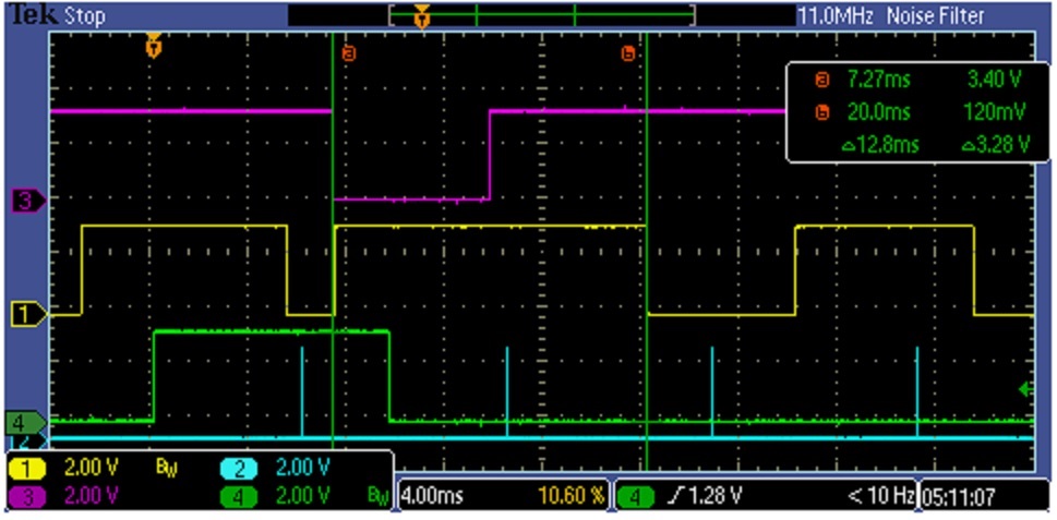
    here is the screenshot

    In the above plot, channel 1 toggles whenever the PWM expires (PWM period) and channel 3 is the actual PWM output. Note that this is configured with TnPWML set to 1 so the PWM is inverted. The duty cycle here is set to the period – 1, so almost 100% duty cycle, I expect the line to stay high for the full cycle (this ties into the problem where if I set the duty cycle to the period, the signal on channel 1 would stop working). At cursor A, the PWM triggers when it shouldn’t, then has a cycle with an abnormally long period and an incorrect duty cycle. In this scenario the PWM values were updated at the start of each cycle and when this glitch occurred the update value was trying to adjust the period by shortening it, so the new period was smaller then the current timer value when the update occurred.

    If I understand correctly this means that trying to emulate the LD_TO_EN bit functionality is SW by doing update when timer expires, actually makes the glitch happen. This actually makes sense since this is exactly what the TRM note warns about: "Altering TnILR to a value smaller than the current counter value may introduce transients ...". It looks like the "safe" time to adjust the PWM parameters is towards the end of PWM period, right? what do you think the best way of doing this would be?

    thanks

    Michael

  • Hi Michael,

    Could you provide the code example you use to test this out so I can see how you initialize and use the PWM driver? Are you setting the "TAMRSU" but of th e "TxMR" register or not?

    Also, it would really help to know the SDK version as there have been many changes over time to multiple drivers.

  • Hi M-W,

    Customer is using SDK 2.30. 

    They need to align PWM to an external signal and use two timers in edge mode to get time difference between PWM and external signal and then use this difference to align them. 

    Here is the configuration code snippet.


           GPTimerCC26XX_Params params;

           GPTimerCC26XX_Params_init(&params);

           params.width = GPT_CONFIG_16BIT;

           params.mode = GPT_MODE_EDGE_TIME_UP;

           zc_edge_timer = GPTimerCC26XX_open(GPTIMER1A, &params);

           zc_pwm_sync_timer = GPTimerCC26XX_open(GPTIMER1B, &params);


           PWM_init();


           PWM_Params_init(&pwmParams);

           pwmParams.idleLevel = PWM_IDLE_HIGH;

           pwmParams.dutyUnits = PWM_DUTY_COUNTS;

           pwmParams.dutyValue = 0;

           pwmParams.periodUnits = PWM_PERIOD_COUNTS;

           pwmParams.periodValue = ZC_DEFAUT_PERIOD_CNTS;

           zc_dim_pwm = PWM_open(PWM0, &pwmParams);


           GPTimerCC26XX_setLoadValue(zc_edge_timer, ZC_CLOCK_PERIOD_CNTS);

           GPTimerCC26XX_setCaptureEdge(zc_edge_timer, GPTimerCC26XX_BOTH_EDGES);

           GPTimerCC26XX_registerInterrupt(zc_edge_timer, zc_edge_timer_int_callback, GPT_INT_CAPTURE);

           GPTimerCC26XX_PinMux pinMux = GPTimerCC26XX_getPinMux(zc_edge_timer);

           PINCC26XX_setMux(zcPinHandle, PIN_ID(PIN_ZC), pinMux);


           GPTimerCC26XX_setLoadValue(zc_pwm_sync_timer, ZC_CLOCK_PERIOD_CNTS);

           GPTimerCC26XX_registerInterrupt(zc_pwm_sync_timer, zc_pwm_sync_timer_int_callback, GPT_INT_CAPTURE);

           EventRegister(EVENT_O_GPT1BCAPTSEL, EVENT_GPT1BCAPTSEL_EV_GPT2A_CMP);


    This bit is to make sure the PWM is updated on the next cycle and to setup the sync timer to capture on the right edge:


           HWREG(GPT2_BASE + GPT_O_TAMR) |= GPT_TAMR_TAILD_TOUPDATE;

           HWREG(GPT2_BASE + GPT_O_TAMR) |= GPT_TAMR_TAMRSU_TOUPDATE;

           HWREG(GPT2_BASE + GPT_O_TAMR) &= ~GPT_TAMR_TACDIR;

           HWREG(GPT2_BASE + GPT_O_CTL) &= ~GPT_CTL_TAPWML;

           GPTimerCC26XX_setCaptureEdge(zc_pwm_sync_timer, GPTimerCC26XX_POS_EDGE);


    TimerSynchronization then is used on the two edge timers to ensure they count off the same clock so the time alignment between PWM and the external signal can be performed. 

    Is this sufficient info?

    thanks

    Michael

  • Hi Michael,

    This is a fairly complex use case, the PWM support in the GP Timers is not as advanced as they could be and some features (like this) could be hard to get just right. In rough numbers, what PWM frequencies and duty cycles are we talking about here?

    Also, based on the code, I assume PW0 is setup for GP Timer 2 and not 0 in the board file?

    Best regards,

    Max
  • Hi Max,

    The PWM frequency is 120Hz with some variations to ensure synchronization. duty cycle can vary from 0 to 100%. Yes, PWM0 is set to GPT2

    thanks
    Michael
  • Hi Michael,

    Are your customer using the sensor controller in the device to do anything as of today? Would it maybe be possible to utilize this instead of the GPTimers? While it does not feature PWM features as such, you could easily implement a software PWM that I would expect you can control to the degree you want relatively easy (considering the frequency is rather low).
  • Hi M-W

    I'll  bring it up with the customer but they already utilize the sensor controller quite extensively...

    thanks

    Michael

  • If not, we need to lock closer on how we could achieve this, if you could get some information on timing requirements I can see if I can test this out myself. Timings that would be interesting is the error between the flank of the sync signal to the beginning of the PWM period along with any other relevant timings.
  • Hi Michael,

    You got any update on this to share?
  • Hi M-W,

    Thank you for the follow-up. We have been trying different ways to delay the PWM update enough to ensure the update value will be bigger than current timer value but with sufficient margin prior to the timer expiration. looks like it is doable. I will let you know if further questions arise.

    thanks
    Michael