This thread has been locked.

If you have a related question, please click the "Ask a related question" button in the top right corner. The newly created question will be automatically linked to this question.

CCS/CC1352R: CC1352: Designed board cannot receive RF signal

Part Number: CC1352R
Other Parts Discussed in Thread: CC1350

Tool/software: Code Composer Studio

Dear Mods and friends,

We have designed our own PCB using CC1352R as the communication chip for both BLE5 and Sub-Ghz. The BLE5 part and related software have run correctly. However, the Sub-Ghz part has not run successfully.

1. We replaced the Balun components as in the LAUNCHPAD with a Balun chip: 0850BM14E0016:
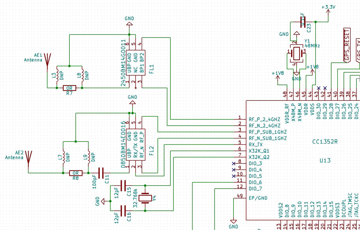
2. Then we used a Wire antenna with a length of 86mm as follow:

3. I tested our Designed board as a Sensor and a launchpad CC1352R as a Collector: This Sensor is Active Scanning (toggle LED each time it calls function sendScanReq). I also measured the frequency that it transmitted with another launchpad (as a network analyzer). It actually can transmit radio signals about 868Mhz. However, this designed board cannot receive any Beacon indication back from the Collector (scanCnfCb does not give any successful status). So at the end, it cannot join the collector's PAN.

4. I tested the designed board with rfEasyLinkRx and rfEasyLinkTx: a. When I turned on the board as rfEasyLinkTx, the network analyzer can detect frequency about 868Mhz but the rfEasyLinkRx - Launchpad cannot receive any packet. Also, when I turned the designed board as rfEasyLinkRx, it cannot receive any packet from the Launchpad- rfEasyLinkTx.

5. Do you have any suggestions for me to improve the matching between this designed board and launchpad CC1352R? 

6. Did we miss any important components that are required to help Sensor be able to join Collector's PAN. 

Really hope to hear any advice soon.

Thank you very much.

  • - Have you checked that you have a tuned antenna? For bench testing this should not have any impact but for later range testing it could.
    - You write "the network analyzer can detect frequency about 868Mhz": Have you measured the frequency accurately? I typical issue with customer board communicating with a launchpad is frequency offset between the two boards.
    - I see from the attached layout snip that your layout is not ideal. The routing from the RF pins to the IPC pins are part of the matching and the length of the lines should be the same as in the ref design. Also the RF_P and RF_N lines should have equal length.
    - See www.ti.com/.../swra629.pdf for a more compact IPC solution.
  • Thank you very much TER
    - I measured the output frequency with a CC1350 Launchpad set up as a Network Analyzer. I am not sure how accurate it is actually.
    - Could you please advise me which equipement i can buy/use to measure the tuning antenna? One VNA with reasonable cost? Any advice how to tune the antenna?
    - Yes, i regconized that our design of the lengths of sinal lines are not ideal. Would you give me more insight (or source) on how it would affect the outcome? I will remake the PCB.
    - I tested 2 of our designed boards as Rx and Tx. They can communicate. That means their antennas are not matched with the launchpad.
    - Please.advise me how to tune this antenna to optimize for 868Mhz. Our board is small: 35mm x 41mm only. Also, we need to operate in both BLE5 and Sub-Ghz.
    Thank you very much
  • "- I tested 2 of our designed boards as Rx and Tx. They can communicate. That means their antennas are not matched with the launchpad. ": No. That means that your boards has a frequency offset compared to the launchpads and you have to find a way to measure the offset.

    For antenna tuning how-to, see chapter 6 in www.ti.com/.../swra161b.pdf

    For layout, follow the ref designs for IPC you are using.

    You write that you have a network analyzer, which one? Isn't this possible to use as a VNA? Else, this could be possible to use: miniradiosolutions.com/.../ or similar.
  • Dear TER,
    "with a CC1350 Launchpad set up as a Network Analyzer": I set up a launchpad cc1350 as the network analyzer. I do not have one VNA yet.
    But if tuning the antenna needs a VNA to see the Smith chart, I am considering to buy one.
    Regarding the frequency offset, I modified the antenna path launchpad cc1352R to be as close as possible to my board: solder the same wire antenna to the launchpad right after C36 and cut out the path after that on the launchpad. However, it still cannot communicate with my board.
    So the only things different between my board and the launchpad that I can think of are: The size of the ground plane and the feed line.
    With your experience, would you think those will make significant changes? Should I make a collector board which has the same size as my board because my board must be small (35mmx41mm )for our applications.
    Thank you very much
  • Frequency offset is not related to the antenna, see the "crystal tuning" part in www.ti.com/.../swra640a.pdf
  • Thank you very much, I have tried tuning the crystal but without an accurate VNA, it is hard to tell the frequency of 2 boards are close to each other.