This thread has been locked.

If you have a related question, please click the "Ask a related question" button in the top right corner. The newly created question will be automatically linked to this question.

CC1201: Unexpected zero data

Part Number: CC1201
Other Parts Discussed in Thread: CC1200DK, CC1200

Hi Team,

My customer got a CC1200DK board and designed their own CC1201 boards based on our reference design. With the same configuration parameter, he got different results:

1.TX&RX using their own CC1201 board

If set  PKT_LEN= 8, there is unexpected packet loss when receiving; Problem can be solved by setting PKT_LEN= 9.

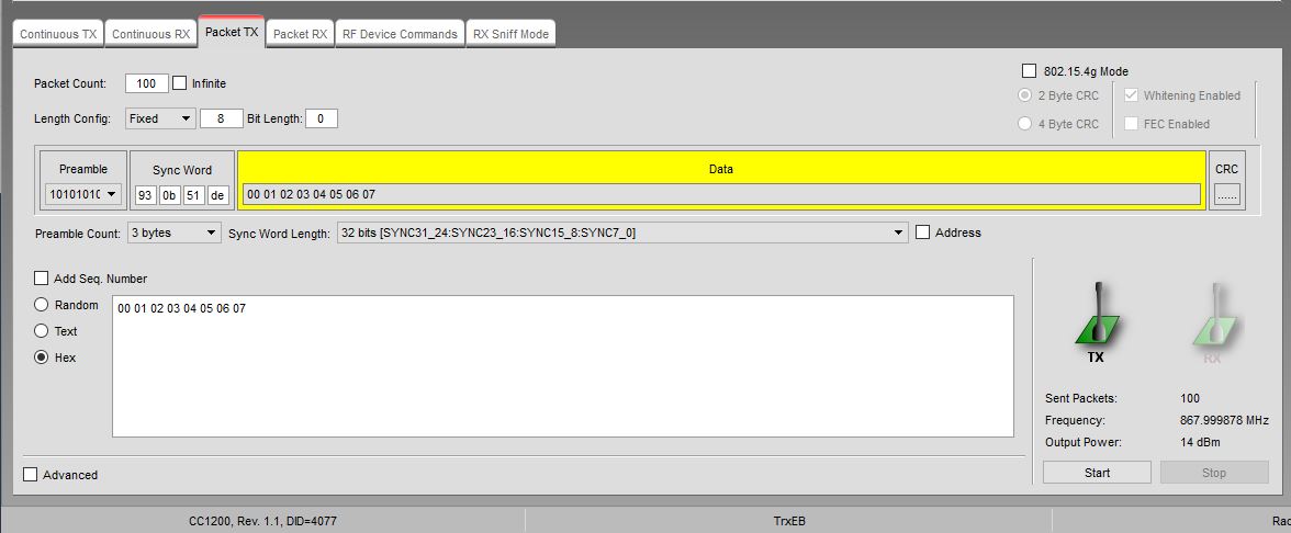
2.TX using their own CC1201 board, RX using TI CC1200 board.

Still need to set the PKT_LEN= 9 to get correct data, but an additional 0x00 will be added in header.

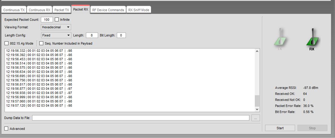
3.TX using TI CC1200 board, RX using their own CC1201 board.

Unexpected packet loss will occur, the PER is about 10%.

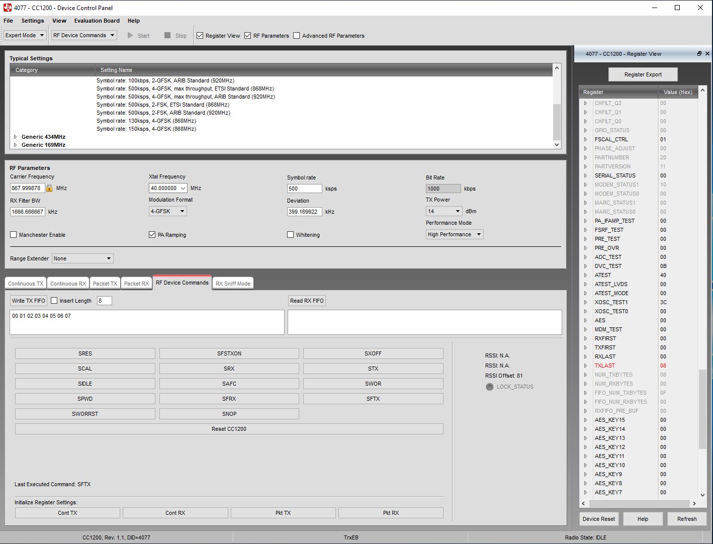
Configurations for cc1200:

static const registerSetting_t preferredSettings[]= 
{
{CC1200_IOCFG2, 0x06},
{CC1200_SYNC_CFG1, 0xA8},
{CC1200_DEVIATION_M, 0x47},
{CC1200_MODCFG_DEV_E, 0x2F},
{CC1200_DCFILT_CFG, 0x1E},
{CC1200_PREAMBLE_CFG0, 0x8A},
{CC1200_IQIC, 0x00},
{CC1200_CHAN_BW, 0x01},
{CC1200_MDMCFG1, 0x42},
{CC1200_MDMCFG0, 0x05},
{CC1200_SYMBOL_RATE2, 0xC9},
{CC1200_SYMBOL_RATE1, 0x99},
{CC1200_SYMBOL_RATE0, 0x99},
{CC1200_AGC_REF, 0x2F},
{CC1200_AGC_CS_THR, 0xF8},
{CC1200_AGC_CFG2, 0x60},
{CC1200_AGC_CFG1, 0x12},
{CC1200_AGC_CFG0, 0x84},
{CC1200_FIFO_CFG, 0x00},
{CC1200_FS_CFG, 0x12},
{CC1200_PKT_CFG2, 0x00},
{CC1200_PKT_CFG1, 0x00},
{CC1200_PKT_LEN, 0x09},
{CC1200_FREQOFF_CFG, 0x23},
{CC1200_MDMCFG2, 0x00},
{CC1200_FREQ2, 0x54},
{CC1200_IF_ADC1, 0xEE},
{CC1200_IF_ADC0, 0x10},
{CC1200_FS_DIG1, 0x04},
{CC1200_FS_DIG0, 0xA3},
{CC1200_FS_CAL1, 0x40},
{CC1200_FS_CAL0, 0x0E},
{CC1200_FS_DIVTWO, 0x03},
{CC1200_FS_DSM0, 0x33},
{CC1200_FS_DVC1, 0xF7},
{CC1200_FS_DVC0, 0x0F},
{CC1200_FS_PFD, 0x00},
{CC1200_FS_PRE, 0x6E},
{CC1200_FS_REG_DIV_CML, 0x1C},
{CC1200_FS_SPARE, 0xAC},
{CC1200_FS_VCO0, 0xB5},
{CC1200_IFAMP, 0x0D},
{CC1200_XOSC5, 0x0E},
{CC1200_XOSC1, 0x03},
{CC1200_PARTNUMBER, 0x20},
{CC1200_PARTVERSION, 0x11},
{CC1200_MODEM_STATUS1, 0x10},
};

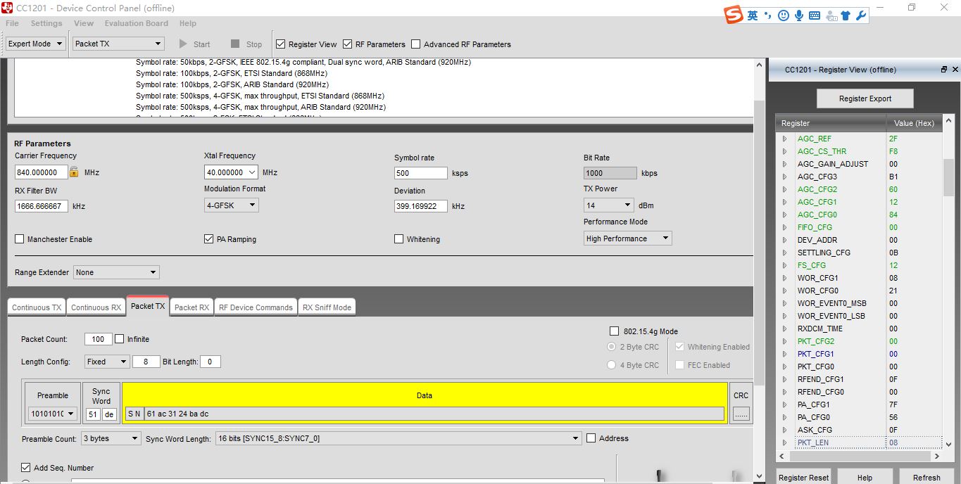
Configurations for CC1201:

static const registerSetting_t preferredSettings[]= 
{
{CC120X_IOCFG2, 0x06}, 
{CC120X_SYNC_CFG1, 0xA8},
{CC120X_DEVIATION_M, 0x47},
{CC120X_MODCFG_DEV_E, 0x2F},
{CC120X_DCFILT_CFG, 0x1E},
{CC120X_PREAMBLE_CFG0, 0x8A},
{CC120X_IQIC, 0x00},
{CC120X_CHAN_BW, 0x01},
{CC120X_MDMCFG1, 0x42},
{CC120X_MDMCFG0, 0x05},
{CC120X_SYMBOL_RATE2, 0xC9},
{CC120X_SYMBOL_RATE1, 0x99},
{CC120X_SYMBOL_RATE0, 0x99},
{CC120X_AGC_REF, 0x2F},
{CC120X_AGC_CS_THR, 0xF8},
{CC120X_AGC_CFG2, 0x60},
{CC120X_AGC_CFG1, 0x12},
{CC120X_AGC_CFG0, 0x84},
{CC120X_FIFO_CFG, 0x40},
{CC120X_FS_CFG, 0x12},
{CC120X_PKT_CFG2, 0x00},
{CC120X_PKT_CFG1, 0x00},
{CC120X_PKT_CFG0, 0x00},//FIX LENGHTH
{CC120X_PKT_LEN, 0x09}, //packet len
{CC120X_FREQOFF_CFG, 0x23},
{CC120X_MDMCFG2, 0x00},
{CC120X_FREQ2, 0x54}, //840M
{CC120X_IF_ADC1, 0xEE},
{CC120X_IF_ADC0, 0x10},
{CC120X_FS_DIG1, 0x04},
{CC120X_FS_DIG0, 0xA3},
{CC120X_FS_CAL1, 0x40},
{CC120X_FS_CAL0, 0x0E},
{CC120X_FS_DIVTWO, 0x03},
{CC120X_FS_DSM0, 0x33},
{CC120X_FS_DVC1, 0xF7},
{CC120X_FS_DVC0, 0x0F},
{CC120X_FS_PFD, 0x00},
{CC120X_FS_PRE, 0x6E},
{CC120X_FS_REG_DIV_CML, 0x1C},
{CC120X_FS_SPARE, 0xAC},
{CC120X_FS_VCO0, 0xB5},
{CC120X_IFAMP, 0x0D},
{CC120X_XOSC5, 0x0E},
{CC120X_XOSC1, 0x03},
}

Questions: 1.Where did the zero byte come from? 

                  2. Why did their boards come into packet loss,is this about hardware design?

Any help will be appreciated.

Best regards,
Viki

  • Packet length 0x8 vs 0x9: What do they actually send? What do they place in the TX FIFO? What do they receive? 

    Why is  CHN_BW set to 0x01 and why are they using zero IF? 

  • Thanks for reply.


    1. PKT_LEN=9 TEST AS FOLLOWS:

    1). TX: our 1201 ,

     PKT_LEN=9; data write in to the write FIFO, as follows:

    0x000x010x020x030x040x050x060x07

    0x010x010x020x030x040x050x060x07

    0x020x010x020x030x040x050x060x07

    0x030x010x020x030x040x050x060x07

    0x040x010x020x030x040x050x060x07


    2)RX: ti 1200DK

    PKT_LEN=9; data read from the read FIFO as follows:

    11:45:25.337 | 00 00 01 02 03 04 05 06 07  |    0

    11:45:25.391 | 00 01 01 02 03 04 05 06 07  |    0

    11:45:25.447 | 00 02 01 02 03 04 05 06 07  |    0

    11:45:25.503 | 00 03 01 02 03 04 05 06 07  |    0

    11:45:25.558 | 00 04 01 02 03 04 05 06 07  |    0

    11:45:25.614 | 00 05 01 02 03 04 05 06 07  |    0

    11:45:25.670 | 00 06 01 02 03 04 05 06 07  |    0

    11:45:25.726 | 00 07 01 02 03 04 05 06 07  |    0

    11:45:25.782 | 00 08 01 02 03 04 05 06 07  |    0


    2. PKT_LEN=8 TEST AS FOLLOWS:

    1). TX: our 1201 ,

     PKT_LEN=8; data write in to the write FIFO, as follows:

    0x000x010x020x030x040x050x060x07

    0x010x010x020x030x040x050x060x07

    0x020x010x020x030x040x050x060x07

    0x030x010x020x030x040x050x060x07

    0x040x010x020x030x040x050x060x07


    2) RX: ti 1200DK

    PKT_LEN=8; data read from the read FIFO as follows:

    17:31:15.449 | 00 00 01 02 03 04 05 06  |    0

    17:31:15.505 | 07 00 01 01 02 03 04 05  |    0

    17:31:15.562 | 06 07 00 02 01 02 03 04  |    0

    17:31:15.617 | 05 06 07 00 03 01 02 03  |    0

    17:31:15.673 | 04 05 06 07 00 04 01 02  |    0

    17:31:15.729 | 03 04 05 06 07 00 05 01  |    0

    17:31:15.787 | 02 03 04 05 06 07 00 06  |    0

    3. CHN_BW=1, CHAN_BW. BB_CIC_DECFACT=1

    Means

    Device

    ADC_CIC_DECFACT

    BB_CIC_DECFACT

    RX Filter BW Range [kHz]

    CC1200

    12

    1 - 44

    37.9 - 1666.7

    CC1201

    12

    1 - 33

    50.5 - 1666.7

    CHN_BW is generated by the SmartRF Studio 7 automatic.

  • To rephrase: Why did you set the RX BW to maximum and also setting zero IF? 

    Are you sure that you send/ set the TX FIFO to what you write?

    I did a test with SmartRF Studio and had no issues getting the correct data with packet length 0x8. 

  • yes, 

    there is no problem when use 2 1200DK communication.

    we use the 

  • we use the SmartRF Studio7 ,expert mode: symbol rate: 500ksps, 4-gfsk,max throughput, etsi stardard 868MHx to generate teh register valuel.
    we donot want to set the zero IF.
    SO I donot known the reason .
    1. our card 1201 TX:
    when i set PKT_LEN=9, then write fifo 8bytes , write the fifo. when finished send, read the Number of bytes in TXFIFO, the result is 0,is it correct?
    when i set PKT_LEN=8, then write fifo 8bytes , write the fifo. when finished send, read the Number of bytes in TXFIFO, the result is accumulate from 0 ,each packet the result is accumulate 1,is it correct?
    2. our card 1201 RX:
    the 1200dk send data, the 1201 receive data.
    the 1201 always read CC120X_MARCSTATE ,denote RX_FIFO_ERROR, so i must send CC120X_SFRX. is it right? when 1201 read correct data from the read fifo, then the CC120X_MARCSTATE is rx_fifo_error.
  • Sorry, didn't see that you used 4-GFSK, then the RX BW is correct. 

    Could you show with screenshots in detail how you do this? 

    As you see, the number of bytes in the TX FIFO is 8, the packet length is also set to 8.

    If you get a FIFIO error in RX you read the wrong number of bytes. 

  • Turing off "add seq number" makes it a bit easier to see what is going on. But this shows that you have a packet length of 8 and hence the PKT_LEN should be set to 0x8. And how does that look on the RX side?

    Why do you use only 2 byte sync? 

  • Any progress? 

  • the picture above is mistake.
    as according to the register value. we use 4 bytes as sync words: 93 0b 51 de .
    we use oure code(our designed cc1201) to send the data to the rx(cc1200DK).
    my code is as follows:
    #define PKTLEN             8
    uint8 txBuffer[PKTLEN+1] = {0};
    static void createPacket(/*uint8 *txBuffer*/)
    {
     uint8 i;
     static int index=0;
     for(i =0; i< (PKTLEN+1); i++)
     {
      txBuffer[i] = i;
     }
     txBuffer[0]=(index++)%256;
     
    }

    void cc120xRunTX()
    {
     cc120xSpiReadReg(CC120X_MARCSTATE, &marcStatus, 1);
     if((marcStatus & 0x1F) == TX_FIFO_ERROR)
     {
      // Flush TX Fifo
       trxSpiCmdStrobe(CC120X_SFTX);
       printf("SFTX times=%d.\n",times);
       times=0;
     }
     else
     {
     
     times++;
     createPacket();
          sendLen=sizeof(txBuffer)-2; //must -2, if -1, then more error data is arrived in the rx.
     printf("send len=%d,\n",sendLen);
     cc120xSpiWriteTxFifo(txBuffer,sendLen);
     trxSpiCmdStrobe(CC120X_STX);
    while(packetSemaphore != ISR_ACTION_REQUIRED);
     // Clear semaphore flag
              packetSemaphore = ISR_IDLE;
     for(uint8 i=0;i<sendLen;i++)
      printf("0x%x,",txBuffer[i]);
     printf("\n");
     
     cc120xSpiReadReg(CC120X_NUM_TXBYTES, &txBytes, 1);
     printf("TXFIFO bytes=%d.\n",txBytes);
      }
     
    }
  • - Why do you do:

    for(i =0; i< (PKTLEN+1); i++)
     {
      txBuffer[i] = i;
     }

    I would assume that the buffer has the length of PKTLEN + 1 after this. 

    - Not sure what you are doing here:

    sendLen=sizeof(txBuffer)-2; //must -2, if -1, then more error data is arrived in the rx.
     printf("send len=%d,\n",sendLen);
     cc120xSpiWriteTxFifo(txBuffer,sendLen);

    What is sendLen when you run this? 

    Have you checked the TX FIFO pointers before and after sending this packet? 

  • Any update?

  • Our card CC1201 received data as follows:

    0xf2,0xf3,0xf4,0xf5,0xf6,0xf7,0xf8,0xf8

    Then receive is RX_FIFO_ERROR.

    I donot known the reason , why??


    2. 

    Our card CC1201 received data as follows:

    0xf1,0xf2,0xf3,0xf4,0xf5,0xf6,0xf7,0xf7

    Then receive is RX_FIFO_ERROR.

    I donot known the reason , why??

  • If you get a RX_FIFO_ERROR you have a FIFO over- or underflow which mean that you have received a different number of bytes than the packet length you have set. 

  • thanks. 

    i set the pkt_len=0x08 in the parameters, {CC120X_PKT_LEN,           0x08},

    In the recv functions: 

    read CC120X_NUM_RXBYTES              0x2FD7  /* Number of bytes in RXFIFO */, the result is 8.

    so i read  8 byte from the RXFIFO.

    i donot know why RX_FOFO_ERROR appear..

    would you pls give  me some suggestions?

    may be somethings is wrong,when i set the  {CC120X_PKT_LEN,=0x08}?

  • THANKS .

    my recv code as follows:

    void cc120xRunRX(SPI_CS_NAME csName)
    {
      static int ticks;
      static uint8 rxBuffer[900] = {0};
      uint8 rxBytes;
      uint8 rxBytes_res;;
      uint8 rxFirst=0;
      uint8 rxLast=0;
      uint8 marcStatus;
      uint8 gpioStatus;
      uint8 retVal=0;
      static uint8 firstFlag=0;
      static uint16 rxIndex=0;
      static uint16 errBit=0;
      static uint16 errPkt=0;
     
     retVal= trxSpiCmdStrobe(csName,CC120X_SRX);
     
     while(1)
     {
     cc120xSpiReadReg(csName,CC120X_MARCSTATE, &marcStatus, 1);
     if((marcStatus & 0x1F) == RX_FIFO_ERROR)
     {
      // Flush RX Fifo
      trxSpiCmdStrobe(csName,CC120X_SFRX);
      printf("SFRX times=%d.\n",ticks);
     }
         // Wait for packet received interrupt
     if(packetRecvSem == ISR_ACTION_REQUIRED)
     {
        retVal= trxSpiCmdStrobe(csName,CC120X_SRX);
       cc120xSpiReadReg(csName,CC120X_NUM_RXBYTES, &rxBytes, 1);
       // Check that we have bytes in fifo
       if(rxBytes != 0)
       {
        // Read n bytes from rx fifo
        cc120xSpiReadRxFifo(csName,rxBuffer, rxBytes); 
        printf("recv len=%d, ticks=%d.",rxBytes,ticks);
        for(uint16 i=0;i<rxBytes;i++)
         printf("0x%x,\n",rxBuffer[i]);
        printf("\n\n");
       }
       // Reset packet semaphore
       packetRecvSem= ISR_IDLE;
       trxSpiCmdStrobe(csName,CC120X_SRX);
      }
     }
    }
  • I have taken the cc120x_easy_link example and modified it to use the 500 kbps settings from Studio and fixed packet length.

    Below are my register settings and the  modified RX and TX functions:

    static const registerSetting_t preferredSettings[]=
    {
      {CC120X_IOCFG2,            0x06},
      {CC120X_SYNC_CFG1,         0xA8},
      {CC120X_DEVIATION_M,       0x47},
      {CC120X_MODCFG_DEV_E,      0x2F},
      {CC120X_DCFILT_CFG,        0x1E},
      {CC120X_PREAMBLE_CFG0,     0x8A},
      {CC120X_IQIC,              0x00},
      {CC120X_CHAN_BW,           0x01},
      {CC120X_MDMCFG1,           0x42},
      {CC120X_MDMCFG0,           0x05},
      {CC120X_SYMBOL_RATE2,      0xC9},
      {CC120X_SYMBOL_RATE1,      0x99},
      {CC120X_SYMBOL_RATE0,      0x99},
      {CC120X_AGC_REF,           0x2F},
      {CC120X_AGC_CS_THR,        0xF8},
      {CC120X_AGC_CFG2,          0x60},
      {CC120X_AGC_CFG1,          0x12},
      {CC120X_AGC_CFG0,          0x84},
      {CC120X_FIFO_CFG,          0x00},
      {CC120X_FS_CFG,            0x12},
      {CC120X_PKT_CFG2,          0x00},
      {CC120X_PKT_CFG0,          0x00},
      {CC120X_PKT_LEN,           0xFF},
      {CC120X_FREQOFF_CFG,       0x23},
      {CC120X_MDMCFG2,           0x00},
      {CC120X_FREQ2,             0x56},
      {CC120X_FREQ1,             0xCC},
      {CC120X_FREQ0,             0xCC},
      {CC120X_IF_ADC1,           0xEE},
      {CC120X_IF_ADC0,           0x10},
      {CC120X_FS_DIG1,           0x04},
      {CC120X_FS_DIG0,           0xA3},
      {CC120X_FS_CAL1,           0x40},
      {CC120X_FS_CAL0,           0x0E},
      {CC120X_FS_DIVTWO,         0x03},
      {CC120X_FS_DSM0,           0x33},
      {CC120X_FS_DVC1,           0xF7},
      {CC120X_FS_DVC0,           0x0F},
      {CC120X_FS_PFD,            0x00},
      {CC120X_FS_PRE,            0x6E},
      {CC120X_FS_REG_DIV_CML,    0x1C},
      {CC120X_FS_SPARE,          0xAC},
      {CC120X_FS_VCO0,           0xB5},
      {CC120X_IFAMP,             0x0D},
      {CC120X_XOSC5,             0x0E},
      {CC120X_XOSC1,             0x03},
    };
    
    static void runTX(void)
    {
        // Initialize packet buffer of size PKTLEN
        uint8 txBuffer[PKTLEN] = {0};
        
        // Set the fixed packet length to PKTLEN
        uint8 writeByte = PKTLEN;
        cc120xSpiWriteReg(CC120X_PKT_LEN, &writeByte, 1);
    
        // Connect ISR function to GPIO2
        ioPinIntRegister(IO_PIN_PORT_1, GPIO2, &radioTxISR);
    
        // Interrupt on falling edge
        ioPinIntTypeSet(IO_PIN_PORT_1, GPIO2, IO_PIN_FALLING_EDGE);
    
        // Clear ISR flag
        ioPinIntClear(IO_PIN_PORT_1, GPIO2);
    
        // Enable interrupt
        ioPinIntEnable(IO_PIN_PORT_1, GPIO2);
    
        // Update LCD
        updateLcd();
    
        // Infinite loop
        while(TRUE)
        {
            // Wait for button push
            if(bspKeyPushed(BSP_KEY_ALL))
            {
                // Continiously sent packets until button is pressed
                do
                {
                    txBuffer[0] = packetCounter++;
                    for (uint8 i = 1; i < PKTLEN; i++)
                    {
                        txBuffer[i] = i;
                    }
               
                    // Write packet to TX FIFO
                    cc120xSpiWriteTxFifo(txBuffer, sizeof(txBuffer));
    
                    // Strobe TX to send packet
                    trxSpiCmdStrobe(CC120X_STX);
    
                    // Wait for interrupt that packet has been sent.
                    // (Assumes the GPIO connected to the radioRxTxISR function is
                    // set to GPIOx_CFG = 0x06)
                    while(packetSemaphore != ISR_ACTION_REQUIRED);
    
                    // Clear semaphore flag
                    packetSemaphore = ISR_IDLE;
    
                    // Update LCD
                    updateLcd();
                    
                    // Wait for a random amount of time between each packet
                    waitMs(3*(rand()%10+3));
                    
                } while (!bspKeyPushed(BSP_KEY_ALL));
            }
        }
    }
    
    
    static void runRX(void) {
    
        uint8 rxBuffer[128] = {0};
        uint8 rxBytes;
        uint8 marcState;
    
        // Connect ISR function to GPIO2
        ioPinIntRegister(IO_PIN_PORT_1, GPIO2, &radioRxISR);
    
        // Interrupt on falling edge
        ioPinIntTypeSet(IO_PIN_PORT_1, GPIO2, IO_PIN_FALLING_EDGE);
    
        // Clear ISR flag
        ioPinIntClear(IO_PIN_PORT_1, GPIO2);
    
        // Enable interrupt
        ioPinIntEnable(IO_PIN_PORT_1, GPIO2);
    
        // Update LCD
        updateLcd();
        
        // Set the fixed packet length to PKTLEN
        uint8 writeByte = PKTLEN;
        cc120xSpiWriteReg(CC120X_PKT_LEN, &writeByte, 1);
    
        // Set radio in RX
        trxSpiCmdStrobe(CC120X_SRX);
    
        // Infinite loop
        while(TRUE) {
    
            // Wait for packet received interrupt
            if(packetSemaphore == ISR_ACTION_REQUIRED) {
    
                // Read number of bytes in RX FIFO
                cc120xSpiReadReg(CC120X_NUM_RXBYTES, &rxBytes, 1);
    
                // Check that we have bytes in FIFO
                if(rxBytes != 0) {
    
                    // Read MARCSTATE to check for RX FIFO error
                    cc120xSpiReadReg(CC120X_MARCSTATE, &marcState, 1);
    
                    // Mask out MARCSTATE bits and check if we have a RX FIFO error
                    if((marcState & 0x1F) == RX_FIFO_ERROR) {
    
                        // Flush RX FIFO
                        trxSpiCmdStrobe(CC120X_SFRX);
                    } else {
    
                        // Read n bytes from RX FIFO
                        cc120xSpiReadRxFifo(rxBuffer, rxBytes);
    
                        // Check CRC ok (CRC_OK: bit7 in second status byte)
                        // This assumes status bytes are appended in RX_FIFO
                        // (PKT_CFG1.APPEND_STATUS = 1)
                        // If CRC is disabled the CRC_OK field will read 1
                        if(rxBuffer[rxBytes - 1] & 0x80) {
    
                            // Update packet counter
                            packetCounter++;
                        }
                    }
                }
    
                // Update LCD
                updateLcd();
    
                // Reset packet semaphore
                packetSemaphore = ISR_IDLE;
    
                // Set radio back in RX
                trxSpiCmdStrobe(CC120X_SRX);
            }
        }
    }

    BR

    Siri