Other Parts Discussed in Thread: CC1352R, CC1350
Hi,
I'm trying to understand the schematic of the Reference Design from the LAUNCHXL-CC1352R1 to design a custom board.
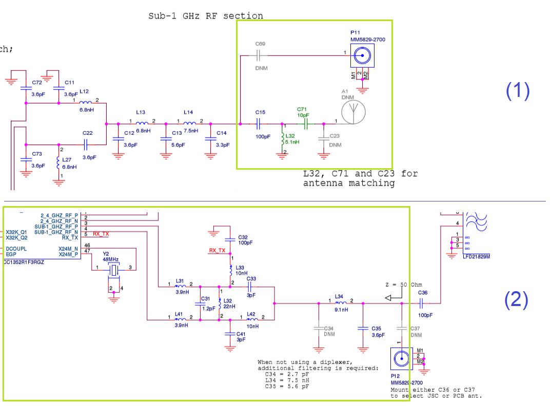
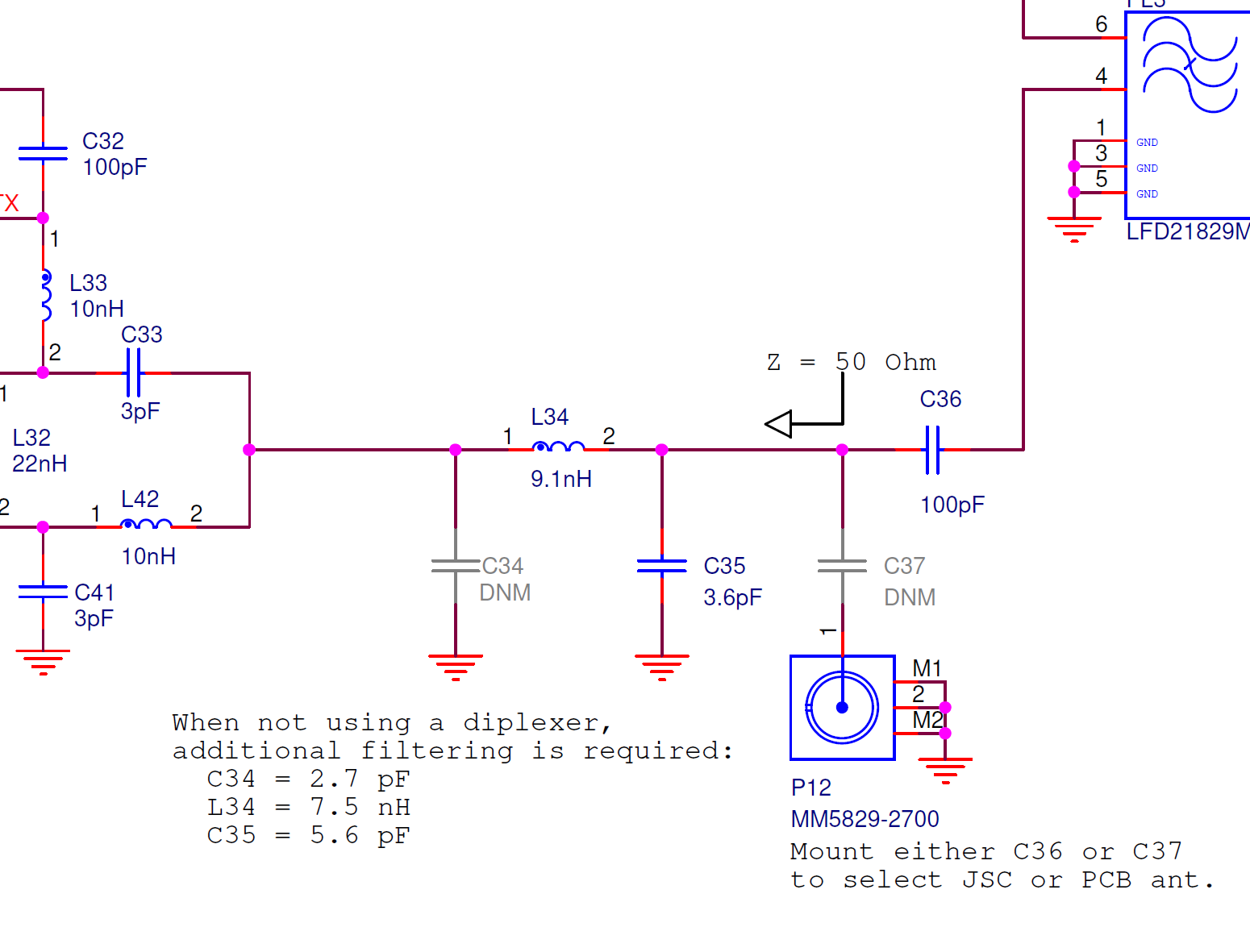
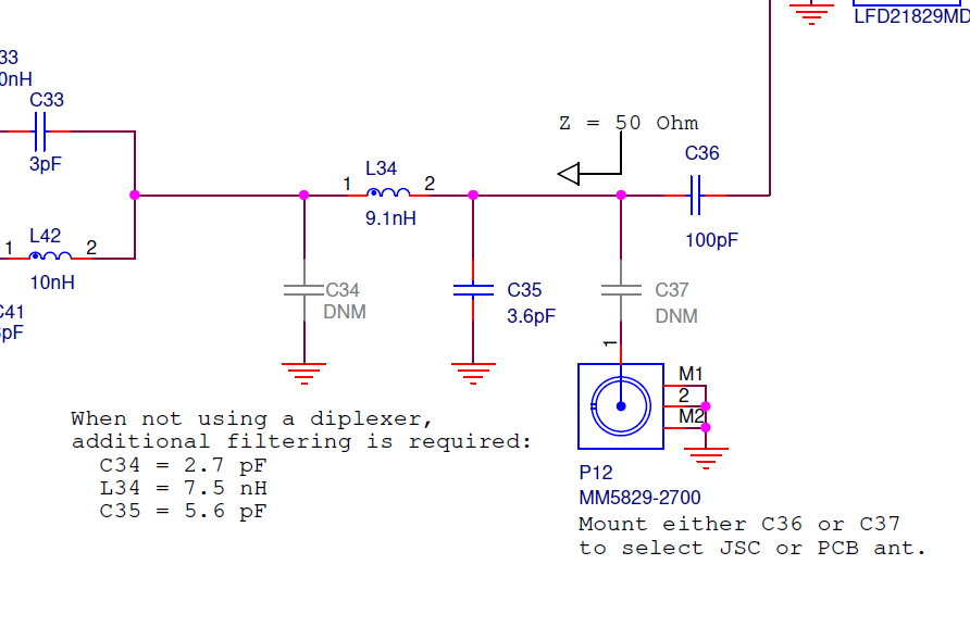
In the WCS038B_Schematic (as shown in the Figure attached) is signalized that after the filter composed by C34 L34 and C35 an impedance of 50 Ohms is present.
When not using a diplexer, additional filtering is required and then changing these components. What is not clear to me is why I should change that without using the diplexer LFD21829MDKED859, once the point measured is the same and the impedance of 50 Ohms indicated in the Figure would not change.
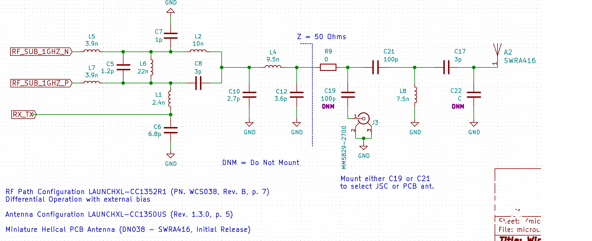
How exactly should be the circuit with the Sub 1GHz path only (i.e. without the 2.4GHz and the diplexer)?
Thanks in advance,
Maurício