This thread has been locked.

If you have a related question, please click the "Ask a related question" button in the top right corner. The newly created question will be automatically linked to this question.

LAUNCHXL-CC1352R1: TIDA-010022 Design: People counting and tracking demo using IWR6843 and sub-1 GHz is not working. All the .out and .patch files are outdated.

Part Number: LAUNCHXL-CC1352R1
Other Parts Discussed in Thread: CC1350, TIDA-010022, , MMWAVEICBOOST

Hi,

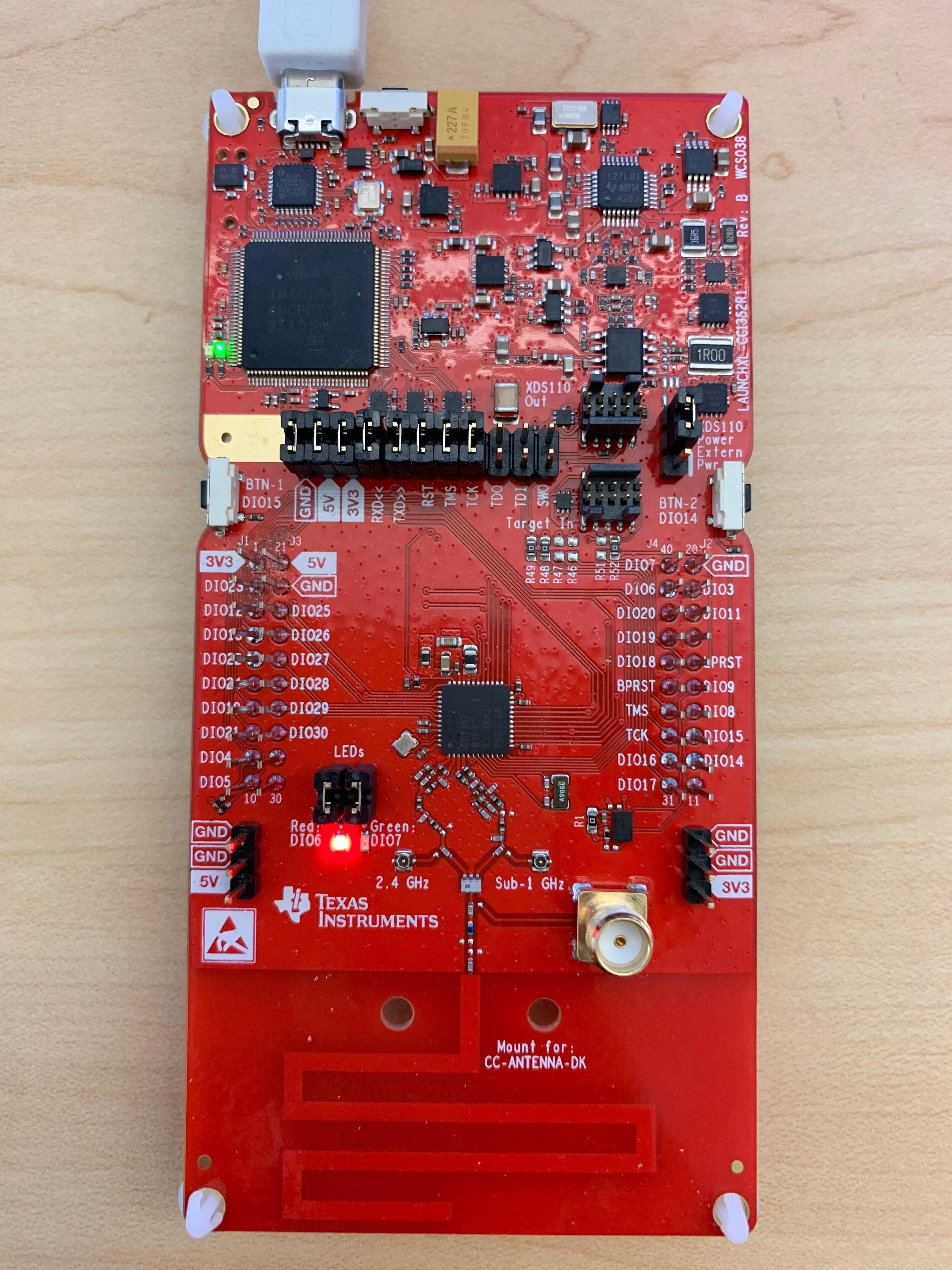
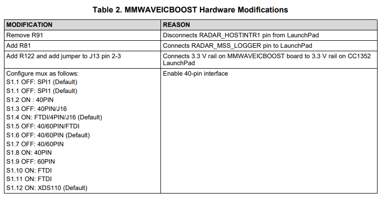
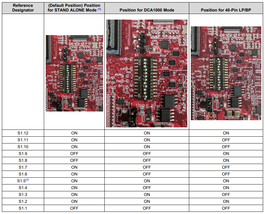
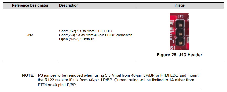
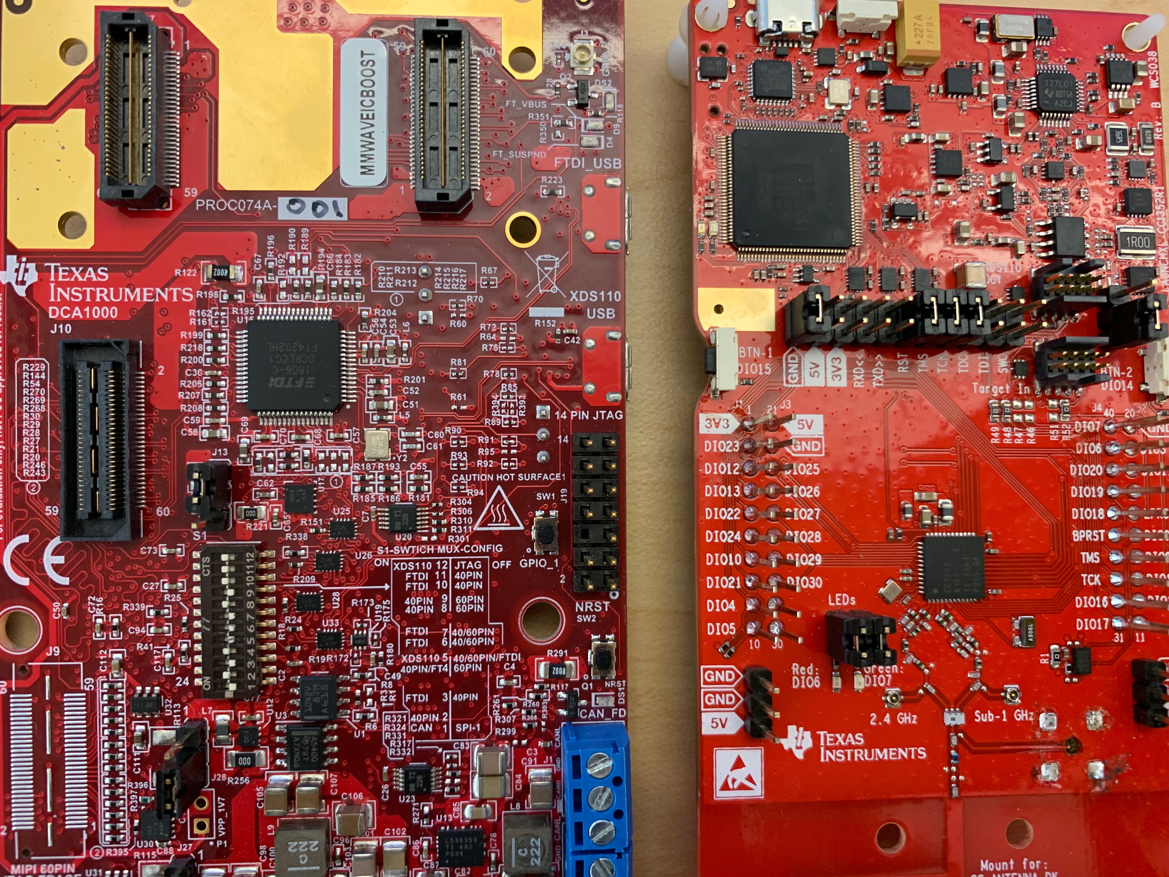
I am testing the people counting and tracking demo using IWR6843 and two CC1352R1 wireless MCU launchpads as explained in design TIDA-010022 (http://www.ti.com/lit/ug/tidued6a/tidued6a.pdf). Please see the hardware changes I made on one of the CC1352 launchpads and mmwaveIC BOOST (Sensor Node). There are no changes made at the Collector end. 

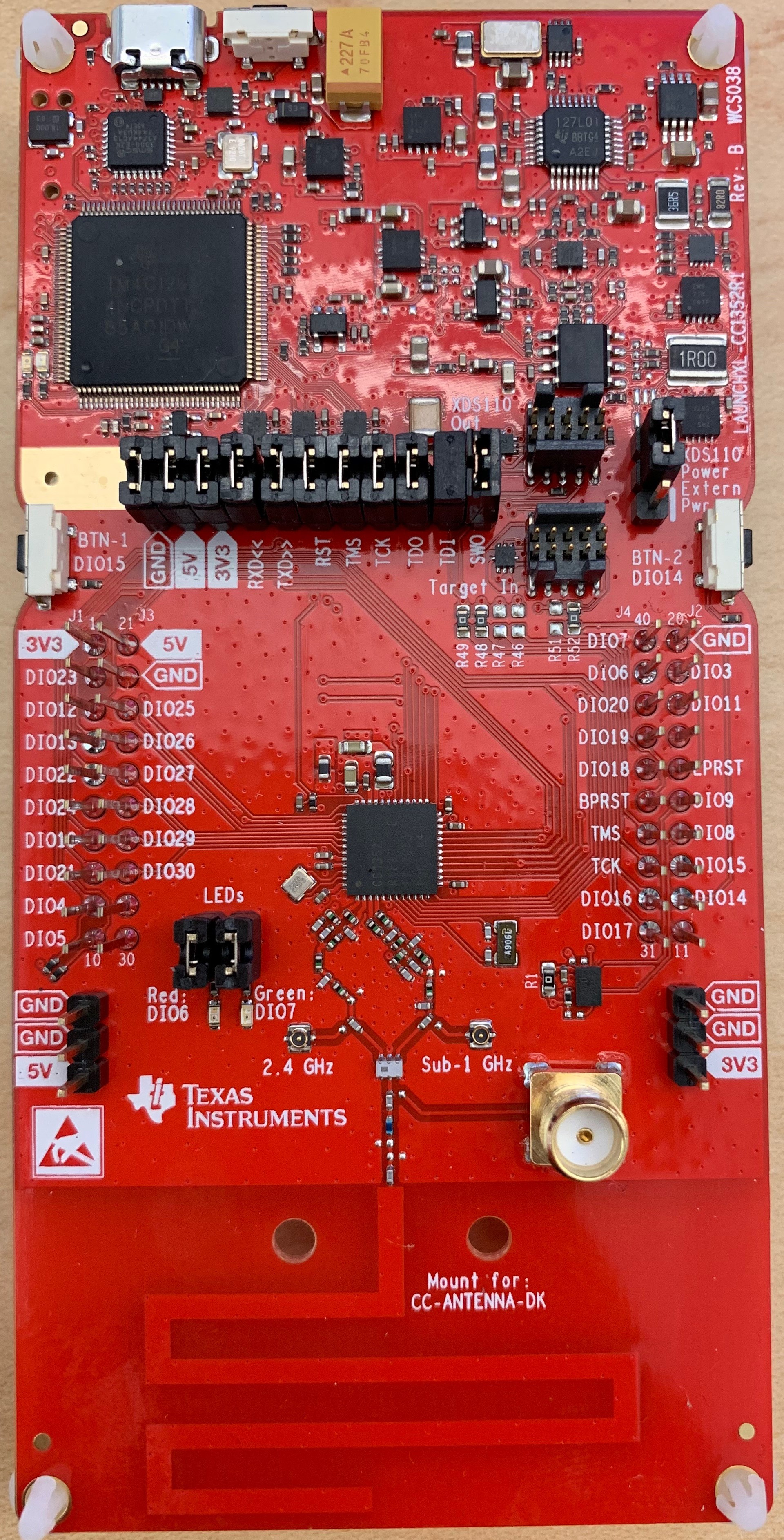
The first problem, I faced is that all the .out files are for SimpleLink CC1352 SDK version 2.10 whereas this SDK version is outdated now. When I flashed these .out images for the collector and sensor node provided in the TIDA-010022 firmware, I don't even see the red LED (DI06) ON on the collector node.

Then I tried to rebuild the firmware of the collector and sensor example codes provided in the SimpleLink-CC13X2-26X2-SDK (v3.30.00.xx) under the TI 15.4 stack. Two patch files for sensor and collector nodes are also for the previous outdated SDK projects. So I manually made changes given in the .patch file for the collector project. I rebuilt it and flashed the .out image using Uniflash, but still I don't see the red LED (DIO6) to be ON. Please find attached the zipped folder of the collector project for you to have a look at.

0486.collector_CC1352R1_LAUNCHXL_tirtos_ccs_syscfg.zip

I am kind of lost in this project so I need your help in this regard:

1) Either Please generate the new .out and .patch files for the updated SDK, so I can run this demo successfully. OR

2) Guide me all the issues in this collector project, and then I can send you the updated sensor project based on the manual changes given in the sensor.patch file at my end and see if I face issues there too.

I saw this forum post related to my project, but they did have a connection established between two CC1352R1 launchpads whereas I could not even make that established.

http://e2e.ti.com/support/wireless-connectivity/sub-1-ghz/f/156/t/801838?RTOS-LAUNCHXL-CC1352R1-The-cc1352r1-sensor-node-does-not-send-commands-to-the-iwr6843isk

Regards,

Attiya

  • Hello Attiya,

    I've asked an expert to look into this, we should have an answer for you in the next few days.

    Cheers,
    Akash
  • Hello,

    I've tried the pre-built binaries multiple times myself and they work as expected.  Therefore, the problem must lie elsewhere.  I reviewed the images you sent and I believe all the hardware modifications are correct.  Can you check a few additional things?

    Attiya Mahmood said:
    I don't even see the red LED (DI06) ON on the collector node.

    This is a good place to start.  If you don't see the LED lighting at all, then it could mean that the collector CC1350 board was not flashed correctly or (worst case) the board is damaged.  Check that 3.3V is getting to the processor side of the board and that the reset line is high.  On your Windows PC (assuming you are using Windows) check that the serial ports show up under device manager when you plug in the board via USB.  You could also use any of the examples given in whichever SDK you prefer to verify the board works.  

    Attiya Mahmood said:
    I saw this forum post related to my project, but they did have a connection established between two CC1352R1 launchpads whereas I could not even make that established.

    Make sure to flash the pre-built binaries as documented in the design guide (section 3.1.2.1). Please check some basic things on the sensor CC1350 LP like power (3.3V) and reset.  The CC1350 communicates with the IWR via UART.  If you have an oscilloscope or logic analyzer you can verify communication is happening by probing DIO12 and DIO13 lines on the CC1350 LaunchPad.

  • Hi,

    I check the power and it is getting 3.3V and the reset line is also high. In the other post, https://e2e.ti.com/support/wireless-connectivity/sub-1-ghz/f/156/t/801838?RTOS-LAUNCHXL-CC1352R1-The-cc1352r1-sensor-node-does-not-send-commands-to-the-iwr6843isk. He faced the same issue and said that these pre-compiled binaries are for SDK2.10 and when we flash them, there is no response or result. Can you please share your binaries (.out files for both sensor and collector node)?

    Interestingly, this community member (https://e2e.ti.com/support/wireless-connectivity/sub-1-ghz/f/156/t/801838?RTOS-LAUNCHXL-CC1352R1-The-cc1352r1-sensor-node-does-not-send-commands-to-the-iwr6843isk) shared his zipped project compiled with SDK 2.40 in the forum and I used his .out files for the sensor and collector launchpads and then I see LED (DI06) turned ON at the collector end but no LED (DI06) turned ON at the sensor node. 

    I still believe something is wrong with the binaries you have provided online inside the firmware design folder. Can you please share the binaries you are using to flash the launchpads?

    Regards,

    Attiya

  • Attiya,

    Ok, I see what's happening.  I didn't realize from your original post images that you have rev E CC1352 silicon.  That revision is not compatible with the SDK v2.10.  More information here.  That's why the binaries won't run on your CC1352 board.  My CC1352 boards are rev. C and the binaries run just fine.  My apologies for missing that point.

    Bottom line: we will have to update the binaries in TIDA-010022 to be compatible with CC1352 rev. E silicon and the latest SDK.  That can take some time however. 

    In the mean time, if you haven't already, I can suggest you try to build the base 15.4 stack sensor and collector projects from SDK v3.30 and flash them on your CC1352 boards to verify your boards are working ok.  Just DON"T apply the patches and DON"T attach the IWR boards.  The read me file in each of the SDK project directories has more information how to run the example code.

  • Hi Gus,

    Okay, so the standard collector and sensor projects are working. Can you help me in providing the patch or give me the directions how to do that.

    Thank you,

    Regards,

    Attiya

  • Attiya,

    This is great!

    The changes to the collector example are minimal and deal with interpreting the data stream sent by the sensor which will eventually send mmWave sensor data.  You should be able to manually add the collector patch changes and rebuild the collector code.  The sensor firmware can remain the same for now.  After re-flashing the collector, it should still come up, create the network, and allow the sensor to join.  

  • Hi Gus,

    I initially did make the manual changes described in the patch file but I could not make them work. However I will try again.

    I was looking for any TI's internal document (If there is any and you are willing to share), which talks about in detail the modifications made in the patch files, so I can understand what I need to do with the newer SDK projects. In any case, I am trying to understand the patches and modifying the projects. If there is NO such document then I may close this thread.

    Thank you,

    Regards,

    Attiya 

  • Hi,

    Is it possible if you can have a look at the collector project? I manually added all the changes in the collector project but again, it doesnot respond (DIO6 is OFF).

    7140.collector_CC1352R1_LAUNCHXL_tirtos_ccs_syscfg.zip

    Attiya

  • Hi Attiya,

    We are trying to get this to work on our side.  We'll get back to you as soon as possible.

  • My apologies for the delay.  It took a few days to get some boards shipped to our site and to modify and test the firmware.  Attached you can find the patches for the sensor and collector as well as the build instructions for the code.  We've tested this on our side and everything works as expected.  Let me know if this works for you and if you have any questions.

    For reference this is what we used for testing:

    - SimpleLink SDK v3.30.00.03

    - CCS v9.2

    - LAUNCHXL-CC1352R1 (silicon rev. E)

    tida_010022_sdk_3_30.zip

  • Hi,

    Thank you for testing it at your end. I highly appreciate it. I will test it at my end and then close the thread.

    Meanwhile I have two quick questions regarding S1 switch settings to enable 40-pin LP/BP interface and the jumper J13. In your TIDA-010022 design, you mentioned these settings for S1:

    However if you look into the mmwaveICBOOST user guide, it mentions the following conflicting settings for S1.9 and S1.11 pins to enable the 40 pin interface. Please explain why did you turn ON the pin S.11 and OFF the pin S1.9 in TIDA-010022 design.

    My second question is regarding J13. When we put jumper on the J13 pin 2-3, the mmwaveICBOOST user guide says to remove P3 jumper (when using 3.3V rail from 40-pin LP/BP interface). Although in the hardware settings, we don't remove P3 Jumper. Kindly elaborate this.

    Thank you,

    Regards,

    Attiya


  • Hi Attiya,

    Attiya Mahmood said:
    Please explain why did you turn ON the pin S.11 and OFF the pin S1.9 in TIDA-010022 design.

    The goal was merely to limit the number of connections between the CC1352 and mmWave device to only those pins that are actually needed to carry out the function of the TI design.  This was done to avoid pin conflicts between the two chips.  You could technically set S.9 to the 40-PIN mode, you would just need to be sure that the pin mux on the CC1352 and mmWave sensor is setup such that there is no conflict (output pin driving output pin for example).  As for S.11, if you set it to 40-PIN mode, the DIO7_GLED and DIO6_RLED on the CC1352 Launchpad will be connected to control signals on the mmWave sensor.  You could always modify the disable LED use on the CC1352 such that this is not an issue or modify the mmWave sensor firmware such that control pins are not used.

    Attiya Mahmood said:
    My second question is regarding J13. When we put jumper on the J13 pin 2-3, the mmwaveICBOOST user guide says to remove P3 jumper (when using 3.3V rail from 40-pin LP/BP interface). Although in the hardware settings, we don't remove P3 Jumper. Kindly elaborate this.

    The ICBOOST design assumes the 3.3V rail will come either from the LaunchPad or the FTDI bus.  In our case, for simplicity, we want the 3.3V rail (and all other rails) to be generated by the ICBOOST.  You could, if you like, remove J13 AND keep R122 as DNP, but you have to make sure the 3.3V rail is generated from the CC1352 Launchpad.  This means keeping the USB cable plugged in to the Launchpad AND the 5V power adaptor plugged into the ICBOOST board.  That would mean you need two power adaptors for the CC1352+mmWave board combo.  

    I hope this clarifies things a bit.

    <EDIT: Corrected typo and added more information for clarification.>