This thread has been locked.

If you have a related question, please click the "Ask a related question" button in the top right corner. The newly created question will be automatically linked to this question.

CC110L: antenna matching for 915Mhz (US market)?

Part Number: CC110L
Other Parts Discussed in Thread: CC1101

Team,

Could you please help with the 4 questions below?

1) Antenna matching:
Can you please confirm that the antenna matching network shown at page 81 of the CC110L datasheet is correct (schematics and RLC values) for 915Mhz operation?
I see the same network (without the optional filter) used on the CC110LEM-868-915-RD so I assume that the datasheet it is correct.

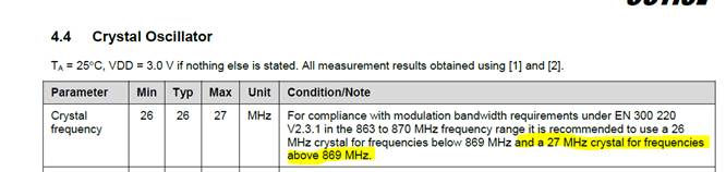
2) Crystal specification:
For 915Mhz can you please confirm that a 27Mhz crystal need to be used?

3) CC110L EM PCB design:
-Was the PCB validated for both 868 and 915Mhz?
-Were both 26Mhz (for 868 Mhz) and 27Mhz (for 915Mhz) crystals used for validation?
-Do you have some recommendation for modification in order to add the optional filter shown at page 81 of the datasheet?

4) CC-ANTENNA-DK-RD antenna kit:
Can the 868/915Mhz PCB antenna designs from the CC-ANTENNA-DK-RD be used as is for CC110L at 915Mhz?

Thanks in advance!

A.

  • 1)

    See chapter 5 (Antenna)  in http://www.ti.com/lit/an/swra640c/swra640c.pdf for a generic antenna match. The reference design and the datasheet assume that an antenna which is matched to 50 ohm is used.

    The schematic drawings in the datasheet should never be used. Always use the reference design: http://www.ti.com/tool/CC1101EM868-915_REFDES

    2) Yes. Or 26.4513 MHz which moves the spurs more out of band and is often a better solution. 

    3) This is shown in http://www.ti.com/tool/CC1101EM868-915_REFDES. The antenna tuning components should be placed after the components shown (between the passives and the PCB antenna)

    4) Yes with the antenna matching components mentioned as part of 1). Note that the required matching is, as one of multiple factors, a function of the ground plane meaning that the antenna should be matched in the final customer product. 

  • Hi Ter,

    Thanks for the answer.

    TER said:

    1) See chapter 5 (Antenna)  in http://www.ti.com/lit/an/swra640c/swra640c.pdf for a generic antenna match. The reference design and the datasheet assume that an antenna which is matched to 50 ohm is used.

    The schematic drawings in the datasheet should never be used. Always use the reference design: http://www.ti.com/tool/CC1101EM868-915_REFDES

    I assume that you mean CC110LEM-868-915-RD since the question is about CC110L. Correct?
    Apparently the CC110LEM-868-915-RD schematics and the CC110L datasheet page 81 show a comparable network (apart from the optional filter).

    TER said:
    3) The antenna tuning components should be placed after the components shown (between the passives and the PCB antenna)

    Thanks for the clarification.
    Was CC110LEM-868-915-RD  PCB validated for 915Mhz using 27Mhz or 26.4513 MHz crystals?
    The BOM from swr082a.zip only lists a 26Mhz crystal.

    Thanks in advance,

    A.

  • CC110L is a version of CC1101 where some functionality is removed but the same reference design can be used for both since the RF part is the same. 

    The only parameter that change if you change xtal frequency is spurs since CC110x have spurs that is a function of the xtal frequency. Hence it's safe to change xtal to what ever frequency you want between 26 MHz and 27 MHz.