This thread has been locked.

If you have a related question, please click the "Ask a related question" button in the top right corner. The newly created question will be automatically linked to this question.

[FAQ] LAUNCHXL-CC1352P: Debugger firmware upgrade failure

Part Number: LAUNCHXL-CC1352P
Other Parts Discussed in Thread: CC1352P, TM4C1294NCPDT, , MSP432E401Y, UNIFLASH

Please note that I am not a developer or hardware engineer, I am using this board to improve my zigbee network using zigbee2mqtt. Apologies in advance for my newbie questions.

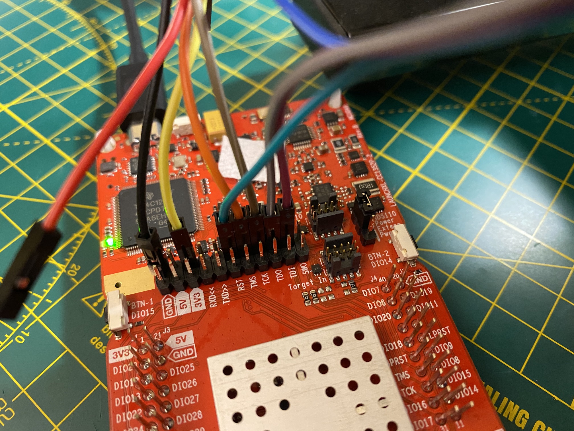
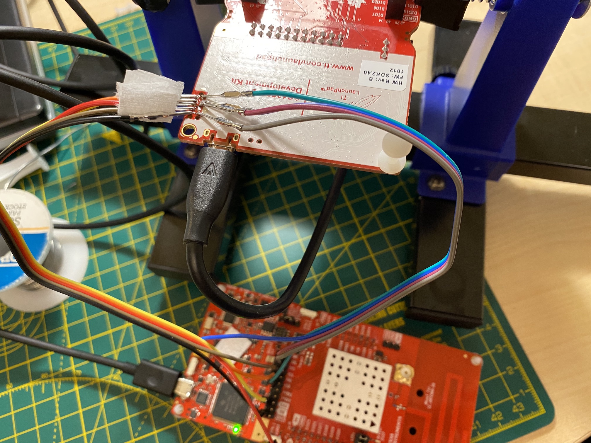
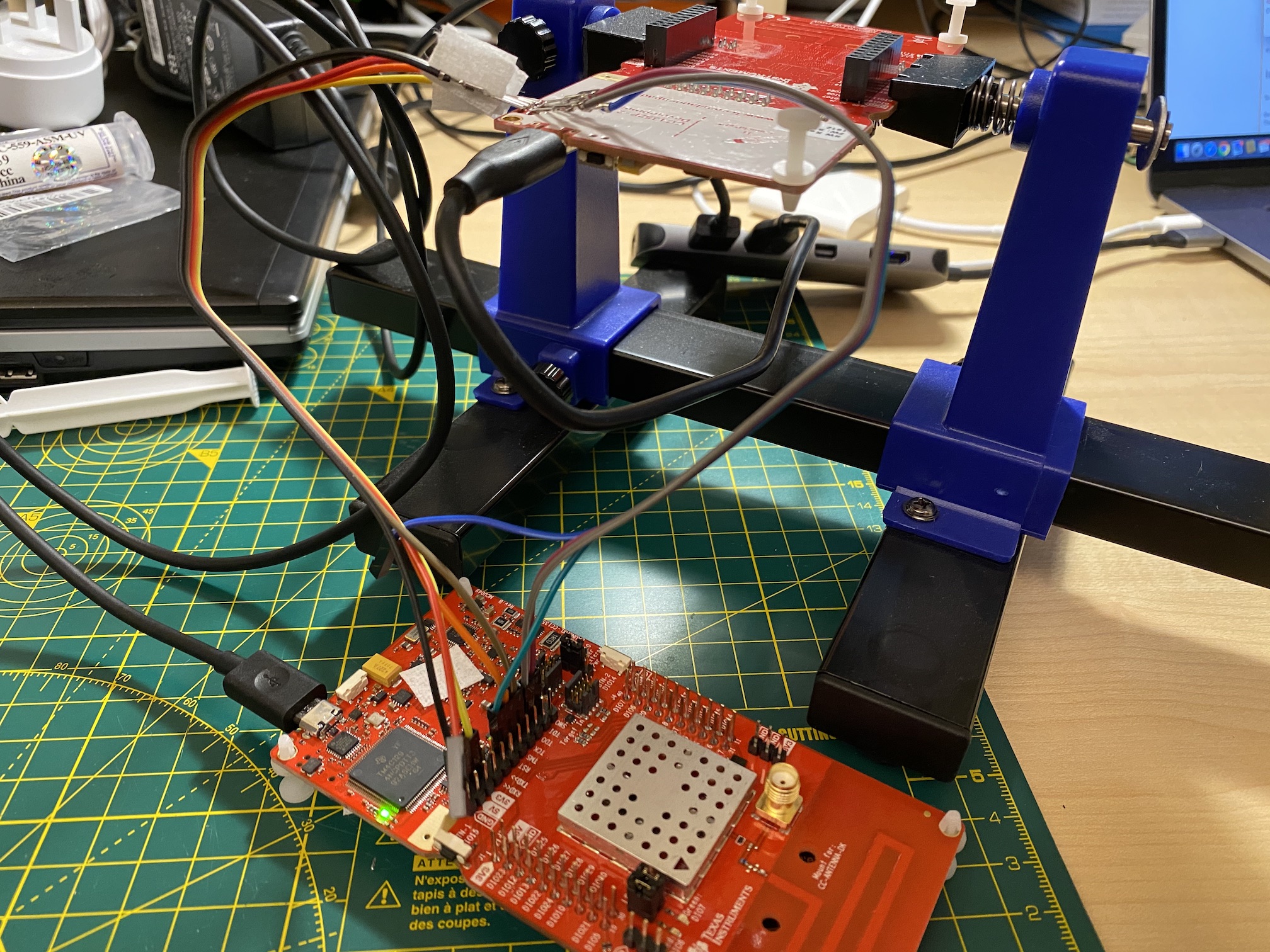
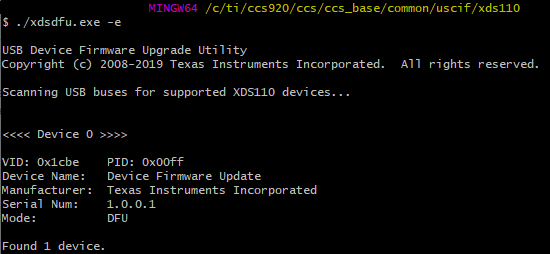
I attempted to flash the CC1352P-2 board on my MacBook via a Windows 10 VM using the FLASH-PROGRAMMER-2 utility. It initially connected ok and prompted me to update the debugger firmware. I selected Yes and then it appeared to disconnect and reconnect, during which time the usual VMware prompt to choose which machine to connect the USB device to appeared. I chose Windows, but by then the firmware update process failed, along with a message saying don't disconnect the board during an upgrade... Yep, I know....

Before it failed the LED lit up on the board when plugging in the USB cable, but now I have no light.

Does anyone know if it's possible to recover from this please? Do I need to connect via serial?

TIA

  • Try to refer to to rescue your LAUNCHXL-CC1352P

  • Thanks for your help - are you saying that i’ll need the debugging module to fix my CC1352P?

  • LAUNCHXL-CC1352P contains XDS110 debugger and you should refer to my link to rescue the XDS110 debugger on LAUNCHXL-CC1352P.

  • Ah thank you, I understand now. The top half of the board is the XDS110 debugger which is then connected to the CC1352 on the lower half of the board via the jumpers.

    So, the problem I seem to have is that no USB device is being detected on Windows (I'm actually using a physical windows 10 machine now rather than a VM - lesson learnt the hard way!). 

    It therefore appears that the "XDS110 needs to be forced into its ROM bootloader" or if that doesn't work "Debugging JTAG" page.

    I'll let you know how it goes - thanks!

  • I'm stuck - do you know where I can find the JTAG TDO pin on the built-in debugger please? I need to connect this to GND to force it into ROM bootloader, but its location isn't obvious.

    Thanks.

  • You can refer to the green circle in the following picture.

  • Sorry I should have said that I thought it was that pin originally - I connected it to GND and plugged in the USB cable, but no connections appeared within Windows Device Manager. I then read that "The JTAG TDO pin to be grounded is part of the TM4C1294NCPDT device, not the GPIO pin that connects to the JTAG TDO pin of the target device." so thought it must be another TDO pin somewhere on the board.

    As you have confirmed this is the correct PIN, it appears I can't even force the debugger into ROM boot loader mode... I'll keep reading but I may be out of options?

  • Just to check, do I need Code Composer Studio v6 or will the latest v9 be ok (I want to check I have the correct drivers installed)

  • Try the following steps first.

    Manual update

    If manual updating or diagnostics is required, using a Windows host is highly recommended. Close any instances of CCS that are running in your system. Open a Windows Command Prompt and issue the following commands:

    1. Go to the directory where the utility is installed:

    C:\>cd C:\ti\ccsv8\ccs_base\common\uscif\xds110

    2. Run the configuration just to make sure a XDS110-class debugger is connected (or to list how many are connected) and what is the firmware revision installed on it: 

    C:\ti\ccsv8\ccs_base\common\uscif\xds110>xdsdfu -e

    3. Put the XDS110 in DFU mode:

    C:\ti\ccsv8\ccs_base\common\uscif\xds110>xdsdfu -m

    4. Run the updater, passing the firmware file and resetting the debug probe afterwards:

    C:\ti\ccsv8\ccs_base\common\uscif\xds110>xdsdfu -f firmware.bin -r

  • Thank you for your continued help.

    Unfortunately xdsdfu -e just reports that no devices were found. I've tried a couple of different USB cables too.

    As far as I can tell, my board appears to dead. :(

  • If you use Flash Programmer 2, can it recognize your LAUNCHXL-CC1352P?

  • If you look on the backside of the board you have connection points to the Tiva/ MSP432 that works as a XDS110. We are in the process of writing a more detailed "how to" on how you can reflash the XDS110. 

  • Rescuing a XDS110 which does not show up on the Computer


    During update of the XDS110 there is a small chance that the device can become bricked. If this happens, the XDS110 chip needs to be reprogrammed. Another device with a XDS110 debugger is needed for reprogramming the bricked device.

    If the device is not a LAUNCHXL-CC26x2 or any of the LAUNCHXL-CC13X2R/P devices, follow the guide found in the troubleshooting chapter of this guide.

    If the device is detected in the computer, jump to the Upgrading firmware part.

    Installing Bootloader

    To reprogram the bricked device, first identify which chip is on the board. It could either be a TM4C1294NCPDT or a MSP432E401Y.

    On the bricked device, locate the TAGCONNECT connector on the backside of the board. This connector holds the JTAG pins for the XDS debugger. The pinout for the TAGCONNECT connector can be found in this image.


    Connect a 10 pin TAGCONNECT connector to this pad or solder wires to the corresponding pins. Connect these pins to a XDS110 debugger. If using another Launchpad, use the upper row of pins going from the XDS, like in this image.

    Connect both the bricked device and the working debugger to your computer. 


    Open UNIFLASH, and In New Configuration, find the XDS110 chip, either TM4C1294NCPDT or a MSP432E401Y. If using the MSP432E401Y, don’t select the BOOTLOADER option.

    In step 2, select Texas Instruments XDS110 USB Debug Probe. Press Start

    UNIFLASH should look like this:


    In the Flash Image(s) selection, navigate to the XDS110 bootloader firmware found in the following CCS installation path:

    ccs****\ccs\ccs_base\common\uscif\xds110\boot_loader.bin

    Press Load Image. The firmware on the bricked device is updated.

    Uniflash should look like this at this step:

    Upgrading firmware

    To get the debugger firmware on the bricked device, the xdsdfu program must be used. Disconnect the other debugger, and make sure that the bricked device is the only one connected.

    Navigate to the same path as the boot_loader firmware was found:

    ccs****\ccs\ccs_base\common\uscif\xds110

    Use your favorite command line and run this command

    ./xdsdfu.exe -f firmware.bin -s L0000000 –r

    This will flash the firmware to the chip and set the Launchpad id to L0000000. Change this number to what is best suited for you.


    Regards, 
    Vegard

  • Thank you very much Vegard for your detailed reply.

    Do you know if a SmartRF 98526 CC debugger could be used to reprogram the CC1352P-2 as I have one of these already? The chip on the debugger is a "SILABS F321 ECL00T 1451"

    If not, I will purchase another CC1352 anyway so once I have that I will attempt to repair the broken one.

    The chip on my Launchpad debugger is a "TM4C1294NCPDT".

  • You have to have XDS110, CC Debugger does not support CC13xx and CC26xx. The cheapest option is to buy a new launchpad and use the XDS110 on this to see if you manage to resurrect your existing one. 

  • Thank you, I shall use a new launchpad to fix my broken one when it arrives in a couple of days time.

  • Hi Vegard/Ter,

    I have attempted to follow the procedure above using another CC1352P-2, but unfortunately it doesn't seem to be working when applying the boot_loader.bin.

    As seen in the photos below, I have soldered wires onto the JTAG pins and plugged the corresponding ones into the working launchpad. I have used a circuit tester to verify there are no shorts between the pins as it is a very tight fit. 

    I then plugged both launchpads into my MacBook via two USB cables and launched UNIFLASH.

    Detected devices showed my working debugger, but ignoring that I went to New Configuration and entered the TM4C1294NCPDT chip name (this is the name printed on the large chip on the debugger). In step 2 I then selected Texas Instruments XDS110 USB Debug Probe and pressed Start.

    I browsed to boot_loader.bin and then pressed Load. The light on my working launchpad flashed and I had a success message, but I saw no light on the broken one. I disconnected both and plugged the broken one into my computer, but still no light. 

    Could you confirm if everything looks ok from my photos please?

  • I would also suggest you to refer to troubleshooting section in dev.ti.com/.../node

  • It looks correct. If you use the xdsdfu program, can you see the broken device listed?

    Vegard

  • I'll try again this evening, but to help me understand the process I have a few questions please:

    Will I need to put the broken launchpad into DFU mode to use the xdsdfu program? If so, do I connect the TDO pin from the TAGCONNECT pads to GND in the same area, or do I use the TDO pin from the jumper pins? Previously I tried connecting the TDO jumper pin on the debugger side to GND on the same set of jumper pins, but that didn't work. Also, should I only plug in the broken launchpad when using xdsdfu?

    Using the flashing method described in your previous post, when I flash the boot_loader.bin firmware, does it update both boards at the same time via the working one? If so why do I need to plug the broken one into my computer via USB? I couldn't see how Uniflash connects to it via USB? Should I see any flashing lights on the broken one during the flashing process? 

    Thank you very much for your time and help with this.

  • When you upload the bootloader through UniFlash, the device will be set in DFU mode automatically. When using XDSDFU, it is easier to only have the broken device connected. 

    Only the broken board will be updated when you update through the good debugger. Uniflash connects to the broken device through the debugger you choose when creating a new session. When you select XDS110 Debug probe, uniflash will use the good debugger to connect to the broken device. 

    You need USB power on both boards, since the debugger isn't able to source enough power through the debugger interface.

    I need to double check how the lights should flash, I will get back to you on this. 

    Vegard

  • During the flashing of the bootloader, the lights on your debugger will flash. When the bootloader is flashed, the broken device will not light up. If you only have the broken device connected at this step, running the xdsdfu utility with -e as an argument should give this as a result:

    It is at this point you should run the xdsdfu command 

    ./xdsdfu.exe -f firmware.bin -s L0000000 –r

    Vegard

  • Great news, it worked! 

    I plugged the broken launchpad into my Windows computer (after following the flashing method via the TAGCONNECT port yesterday) and luckily it detected the Stellaris device! I then flashed the firmware.bin file using ./xdsdfu.exe -f firmware.bin -s L0000000 –r, and it came back to life. 

    I guess what threw me was the statement that said "The firmware on the bricked device is updated and the LED should now light up" as I saw no light after flashing boot_loader.bin. It appears that no light might be normal, and that I should just proceed with flashing firmware.bin.

    Thank you all very much for your help!