This thread has been locked.

If you have a related question, please click the "Ask a related question" button in the top right corner. The newly created question will be automatically linked to this question.

CC1352P: Can't enter standby power-mode although the documentation allows

Part Number: CC1352P

Hi,

I was trying to make the CC1352P enter standby mode. I suspended all tasks and then i measured ~0.5mA which is what should get when the processor is in Idle mode.

  • The clock in my system is: CCFGREAD_SCLK_LF_OPTION_XOSC_LF 
  • So in function  Power_init()  the driver choose to disallow standby mode and sets it: Power_setConstraint(PowerCC26XX_DISALLOW_STANDBY); 
  • When the driver should change its power mode in function PowerCC26XX_standbyPolicy() it cant enter standby and therefore doesn't run the line : Power_sleep(PowerCC26XX_STANDBY);   

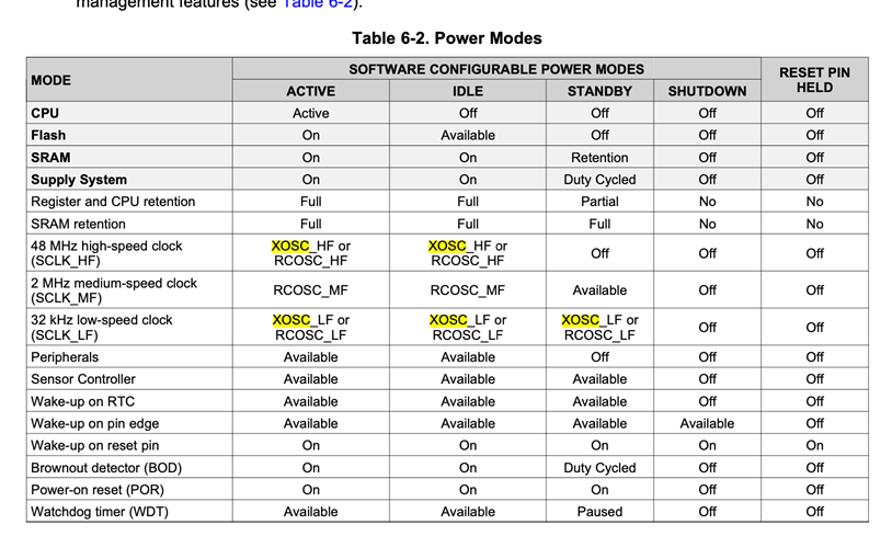
This is not the whole story. In TI's datasheet SWRS192C there is the following table, which shows that in standby-mode the 48 MHz clock is off, meaning M4 is off, and that is what i wanted. It doesn't mention and limitation on entering this mode.

So what am I missing and I need to do in order make the processor enter standby-mode?

thank you,

Adi

  • Hi Adi,

    You are correct in that Power_init() sets constraints, these are however released again as the clock qualifiers etc. are done.

    You should get closer to 600-700mA when the CPU are only in idle. numbers below that most likely mean there is peripherals running and not the CPU per say. Generally when working with TI-RTOS, you don't need to do anything yourself to go into standby. If possible to enter standby (possible being from the SW point of view), then it will enter standby.

    Consider what you do in the tasks that you "suspend". For example, leaving the UART driver "on" in a non-blocking RX could for example prevent you from idle, no matter if your tasks are blocked or not. To fully enter standby, most drivers used also need to be idle/not in use. I would recommend you try out the pinStandby example. This is a good example to use to test and verify that your measurement setup is ok.

  • Hi,

    The constrains are indeed set during Power_init() but they are never cleared. I see them during the FW's steady-state. 

    My original question referred to measurements of 580uA which fits your numbers of IDLE mode (and the driver configuration that i see).

    Again, according to your documentation the processor should be able to get into stand-bye mode.

    What is expected to happen at clock qualifiers?

    When the clock qualifiers run/being set?

    What should i do to make them run?

    When I cleared the DISABLE_STANDBY at the end of my boot, and closed the tasks i saw 300uA. That is indication to standby-mode and peripherals which are not shutdown properly. 

    Any ideas why my FW stays with DISABLE_STANDBY  ?

    BR,

    Adi

  • Hi Adi,

    The qualification step could be seen as "wait until clocks are ready" step. For example, if you have set the device to use XOSC_LF, the driver would wait for the HW to inform you that the clock is "OK" (this is a simplification).

    This is something the power driver does during the init call (which is usually done at the beginning of main) as it also controls the clock switching in the application. You should do nothing in regards to this, the driver takes care of it all. 

    Are you running on a LaunchPad or your own custom hardware? Also, which software are you running, have you tried the "pinStandby" example?

  • Hi M-W,

    Thanks for the qualifiers explanation.

    I am running my FW which calls the power driver init function at the beginning of main. The test is done on TI's LaunchPad.

    I haven't tested "pinStandby" since i had problem building it, the template seems broken.

    The thing is that power_init should have finished its business without DISALLOW settings, even when i am running with CCFGREAD_SCLK_LF_OPTION_XOSC_LF configuration.

    The parts i saw in the power driver are consistent with configuring the DISALLOW.

    The question is where in the init flow you clear the disallow and according to which condition? If it should have been OK and get into standby, then something prevents the power init from going in the path you planed. 

    any ideas?

    BR,

    Adi

  • Hi Adi,

    The release is part of the expected interrupt signaling that the qualifiers are done:

    oscillatorISR -> disableLFClockQualifiers

    I very much doubt there is something wrong with the example template as such. It is more likely that it is related to your installation path. Could you maybe share some information on which SDK you are using , what errors you see when building and which tool chain you use. 

    "The thing is that power_init should have finished its business without DISALLOW settings, even when i am running with CCFGREAD_SCLK_LF_OPTION_XOSC_LF configuration."

    This is not true, it needs the settings as the device needs to stay out of standby during the qualification. Could you maybe share exactly how your main is setup?

  • Hi M-W,

    1. I didn't change the default configurations such as PowerCC26X2_module or PowerCC26X2_config so i guess i shouldn't be influencing the driver to config DISALLOW_STANDBY

    2. My FW begins with the following code.

    I will say again that i see that the power constrain is DISALLOW_STANDBY after Board_init(). 

    int main(void)
    {
       DMMPolicy_Params dmmPolicyParams;
       DMMSch_Params dmmSchedulerParams;
       Task_Params params ;
       FIFO_DB_CFG fifoConfig = {
          .pCbCriticalEnter = _criticalEnter,
          .pCbCriticalExit = _criticalExit,
       };

       RegisterAssertCback(AssertHandler);


       Board_init();

       ...
    }

    void CC1352P1_LAUNCHXL_initGeneral(void)
    {
       Power_init();

       if (PIN_init(BoardGpioInitTable) != PIN_SUCCESS) {
          /* Error with PIN_init */
          while (1);
       }

       /* Perform board-specific initialization */
       Board_initHook();
    }
    /*
    * ======== Board_init ========
    */
    void Board_init(void)
    {
       CC1352P1_LAUNCHXL_initGeneral();
    }

    3. I didn't mean to question your example code, I wanted to say that it is not working at my environment. 

       a. The installed SDK is 3_10_01_11 

       b. when i open the template i am asked to save it into different directory and then i get the message: Non-recognized options were detected in the project file

       c. The workspace is finally opens, but when i click on the files (in the workspace view) the links are broken since the file path is wrong.

       d. I tried building anyways and got:

       e. I tried copying the files to the workspace path but the env problems didnt finish.

    BR,

    Adi

  • Hi Adi,

    When using IAR there is more steps to it than simply importing the project, You for example also need to add in the "custom argument variables" for it to be able to build. please see the following quick start quide, hopefully it could guide you to getting it to compile:

    http://dev.ti.com/tirex/explore/node?node=AE7RAnqQArlbuhRki8hahA__pTTHBmu__LATEST

    The power driver could keep the constraint until after Board_init(), it does not block on qualification, it simply sets up the interrupt so that it can react to it when it is done. As you are using a LP, I do not think there is anything wrong with your clock setup. This is why I would like you to try out the "pinStandby" example to verify the behavior. I hope it will become easier with the help of the quick starter guide. Unfortunately, working in IAR is not as trivial as working with for example CCS (which is more integrated with the SimpleLink ecosystem) and requires a bit more tinkering. 

  • Hi Adi,

    I got a notification saying you had answer to this thread but there seems you later removed the post. Is there any updates on this from you that should be here that is not visible for some reason?

  • Hi M-W,

    I wrote that the i couldn't build the example at CCS and sent you the error message, but then i downloaded a new version of CCS and the compilation problems finally got solved. 

    However, even when i run the pinStandby example i couldn't measure the expected standby-mode power consumption of ~1uA. 

    * I am using CC1352P1 Development Kit, I built the project and burned the FLASH.

    * I saw the FW running, and the LEDs blinked every 5 seconds.

    * Then I disconnected all the jumpers that connect the MCU to the debugger, and also the LED jumpers. At this point the cpu is suppose to be "stand alone".

    * The power measurements showed that during awake time the consumption is 3.3mA and during sleep it is 300uA. 

    Is this the expected result?

    BR,

    Adi

  • Hi Adi,

    Ok.

    No, 300 uA is not correct, what are you using to measure the consumption? Have you seen this application note on the subject?

    www.ti.com/.../swra478

  • Hi M-W,

    Although most of my setup's configurations were correct, when i went over all of them with the document, i got similar results and graphs as seen there.

    I think the sampling resolution and overall test-time made the difference. 

    However i still have question - how come the min value is negative (and not 0)?

    Thank you,

    Adi

  • Hi Adi,

    The negative values are a matter of measurement theory, there could be several reasons to this such as ground bonce, ringing, impedance miss-match etc. For example, in the case of the pictures, you could have very (very) small negative transients related to (for example) some fast switching on the device. While these are so small they don't really affect the long time average, they would still set the number for the absolute minimum value recorded.