This thread has been locked.

If you have a related question, please click the "Ask a related question" button in the top right corner. The newly created question will be automatically linked to this question.

CC2652R: GPTimerCC26XX Timeout interrupt when in GPT_MODE_EDGE_TIME_UP

Part Number: CC2652R
Other Parts Discussed in Thread: SYSCONFIG

I am using  GPTimerCC26XX in GPT_MODE_EDGE_TIME_UP to measure the mark/space time of an input signal. I am getting the interrupts as expected on the positive and negative edges, however I want to correct for the timer wrap around so I am trying to get an interrupt when the timer resets. I thought GPT_INT_TIMEOUT would work but it doesn't seem to cause an interrupt. Is it possible to get a timeout interrupt in this mode and if so what am I doing wrong?

Code snippets:

GPTimerCC26XX_Params params;
GPTimerCC26XX_Params_init(&params);

params.width = GPT_CONFIG_16BIT;
params.mode = GPT_MODE_EDGE_TIME_UP;
params.debugStallMode = GPTimerCC26XX_DEBUG_STALL_OFF;
inputTimer1 = GPTimerCC26XX_open(CONFIG_GPTIMER_0, &params);

GPTimerCC26XX_registerInterrupt(inputTimer1, timerCallback1, GPT_INT_CAPTURE | GPT_INT_TIMEOUT);


GPTimerCC26XX_PinMux pinMux = GPTimerCC26XX_getPinMux(inputTimer1);
PINCC26XX_setMux(hGpioPin, pins[0], pinMux);

GPTimerCC26XX_setCaptureEdge(inputTimer1, GPTimerCC26XX_BOTH_EDGES);
GPTimerCC26XX_setLoadValue(inputTimer1, 0xFFFFFF);

GPTimerCC26XX_start(inputTimer1);

static void timerCallback1(GPTimerCC26XX_Handle handle, GPTimerCC26XX_IntMask interruptMask)
{
    if (interruptMask & GPT_INT_CAPTURE)
    {
         //...
    }

    if (interruptMask & GPT_INT_TIMEOUT)
    {
        //...
    }

}

Thanks, Martin

  • Hi Martin,

    The timeout interrupt is unfortunately only possible in one-shot / periodic mode, not the counting modes. An workaround for this could be to setup an additional periodic/one-shot timer that you sync with the edge timer. You could then reset this during edge interrupts and use it to detect wraparounds in between edges.

  • yes I started to come to that conclusion, I thought the TRM implied that you could get an interrupt but wasn't sure.

    I tried exactly what you suggest, I need to measure 3 inputs so I used GTP1A, GPT1B, GPT2A to capture the edges and GPT2B in periodic mode.  The GPTimerCC26XX doesn't support synchronisation so I tried just using TimerSynchronize() which was close but the timers were not exactly synchronised, only off by a small amount I think around 100 from memory.

    Should I expect to be able to exactly synchronise the timers or is this the best it gets?

  • Hi Martin,

    You should be able to run the timers fully in sync, the sync call should cause a one-shot reset of all timers at once. Note that the timers in synchronized in terms of the reset and count value (they are all driver by the same clock). When you say they are off by ~100, what numbers are you looking at more exactly?

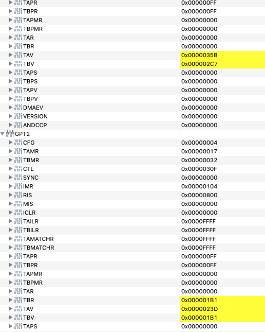
  • I am setting a break point in the timeout interrupt callback and then just looking at the TAV,TBV values in the registers tab. It might just be the timing when debugger is reading the registers, although I have turned GPTimerCC26XX_DEBUG_STALL_ON. I'm using the following code to sync, where timer1,timer2,timer3 are in GPT_MODE_EDGE_TIME_UP mode and timer4 is in GPT_MODE_PERIODIC_UP mode. 

    GPTimerCC26XX_start(timer1);   //GPT1A
    GPTimerCC26XX_start(timer2);   //GPT1B
    GPTimerCC26XX_start(timer3);   //GPT2A
    GPTimerCC26XX_start(timer4);   //GPT2B

    TimerSynchronize(GPT0_BASE, TIMER_1A_SYNC | TIMER_1B_SYNC | TIMER_2A_SYNC | TIMER_2B_SYNC);

    This is an example of what I see in the debugger:

    Also is it possible to determine what edge caused an interrupt when using GPTimerCC26XX_BOTH_EDGES? 

  • Could you share the full setup of the timers (all together) so the settings behind all this is clear. The behavior of the TAV/TBV register (among some) is slightly different depending on which modes each timer is in. If i knew exactly how the four timers is configured I could give some better insight (sharing an example I could run is even better).

    As for detecting which edge caused an interrupt, the only way to is read the GPIO value during the interrupt. 

  • I've attached some simplified code below. CONFIG_GPTIMER_X are setup using SysConfig to create 4 16bit timers using GPTM1, GPTM2.

    It's not a big issue just something I noticed when debugging. 


    static uint8_t pulseInputPins[4] = { IOID_23, IOID_24, IOID_25, IOID_26};
    
    static GPTimerCC26XX_Handle timer1, timer2, timer3, timer4;
    int dbg;
    
    static void timerCallback1(GPTimerCC26XX_Handle handle, GPTimerCC26XX_IntMask interruptMask) {}
    static void timerCallback2(GPTimerCC26XX_Handle handle, GPTimerCC26XX_IntMask interruptMask) {}
    static void timerCallback3(GPTimerCC26XX_Handle handle, GPTimerCC26XX_IntMask interruptMask) {}
    
    static void timerCallback4(GPTimerCC26XX_Handle handle, GPTimerCC26XX_IntMask interruptMask)
    {
    	dbg++;		//!! breakpoint here
    }
    
    
    static GPTimerCC26XX_Handle initEdgeTimer(unsigned int index, GPTimerCC26XX_HwiFxn callback)
    {
    	GPTimerCC26XX_Params params;
    	GPTimerCC26XX_Params_init(&params);
    
    	params.width          = GPT_CONFIG_16BIT;
    	params.mode           = GPT_MODE_EDGE_TIME_UP;
    	params.debugStallMode = GPTimerCC26XX_DEBUG_STALL_ON;
    
    	GPTimerCC26XX_Handle timer = GPTimerCC26XX_open(index, &params);
    	GPTimerCC26XX_registerInterrupt(timer, callback, GPT_INT_CAPTURE);
    	GPTimerCC26XX_PinMux pinMux = GPTimerCC26XX_getPinMux(timer);
    	PINCC26XX_setMux(hGpioPin, pulseInputPins[0], pinMux);
    	GPTimerCC26XX_setCaptureEdge(timer, GPTimerCC26XX_BOTH_EDGES);
    	GPTimerCC26XX_setLoadValue(timer, 0xFFFFFF);
    
    	return timer;
    }
    
    void pulseInputsInit(const uint8_t *pins)
    {
    	timer1 = initEdgeTimer(CONFIG_GPTIMER_0, timerCallback1);
    	timer2 = initEdgeTimer(CONFIG_GPTIMER_1, timerCallback2);
    	timer3 = initEdgeTimer(CONFIG_GPTIMER_2, timerCallback3);	
    
    		//wrap around counter
    	GPTimerCC26XX_Params params;
    	GPTimerCC26XX_Params_init(&params);
    
    	params.width          = GPT_CONFIG_16BIT;
    	params.mode           = GPT_MODE_PERIODIC_UP;
    	params.debugStallMode = GPTimerCC26XX_DEBUG_STALL_ON;
    
    	timer4 = GPTimerCC26XX_open(CONFIG_GPTIMER_3, &params);
    	GPTimerCC26XX_setLoadValue(timer4, 0xFFFFFF);
    	GPTimerCC26XX_registerInterrupt(timer4, timerCallback4, GPT_INT_TIMEOUT);
    
    
    	GPTimerCC26XX_start(timer1);
    	GPTimerCC26XX_start(timer2);
    	GPTimerCC26XX_start(timer3);
    	GPTimerCC26XX_start(timer4);
    
    	TimerSynchronize(GPT0_BASE, TIMER_1A_SYNC | TIMER_1B_SYNC | TIMER_2A_SYNC | TIMER_2B_SYNC);
    }
    

  • Hi,

    I tested this out and while it looks like it does not work (by inspecting the registers), I could verify that the reset actually happens by reading out the values in SW. I'm unsure on why it does not update as expected when reading the register from CCS.

    You could try it out yourself and see how it looks for you:

        #include <ti/devices/DeviceFamily.h>
        #include DeviceFamily_constructPath(inc/hw_gpt.h)
        volatile uint32_t before[4];
        volatile uint32_t after[4];
    
        before[0] = HWREG(GPT0_BASE + GPT_O_TAR);
        before[1] = HWREG(GPT1_BASE + GPT_O_TAR);
        before[2] = HWREG(GPT2_BASE + GPT_O_TAR);
        before[3] = HWREG(GPT3_BASE + GPT_O_TAR);
        TimerSynchronize(GPT0_BASE, TIMER_0A_SYNC | TIMER_0B_SYNC | TIMER_1A_SYNC | TIMER_1B_SYNC |
                                        TIMER_2A_SYNC | TIMER_2B_SYNC | TIMER_3A_SYNC | TIMER_3B_SYNC);
        after[0] = HWREG(GPT0_BASE + GPT_O_TAR);
        after[1] = HWREG(GPT1_BASE + GPT_O_TAR);
        after[2] = HWREG(GPT2_BASE + GPT_O_TAR);
        after[3] = HWREG(GPT3_BASE + GPT_O_TAR);


    My test was setup for 4 periodic counters (using all GP modules just for testing).

  • ok, thanks for looking into it.