This thread has been locked.

If you have a related question, please click the "Ask a related question" button in the top right corner. The newly created question will be automatically linked to this question.

CCS/LAUNCHXL-CC1352P: Is it MSP432E401Y or TM4C1294NCPDT on CC1352P launchpad?

Part Number: LAUNCHXL-CC1352P
Other Parts Discussed in Thread: CC1352P, MSP432E401Y, UNIFLASH, LAUNCHXL-CC1310

Tool/software: Code Composer Studio

Hi team,

My customer is a dev kit maker, their products integrate our CC1352P & XDS110 (MSP432E401Y). They programmed MSP432E4 with our XDS110 firmware but the XDS110 seems not working properly. Do you think it's because it is not TM4C129?

The programmed image can be found at 

C:\ti\ccs1010\ccs\ccs_base\common\uscif\xds110\boot_loader.bin

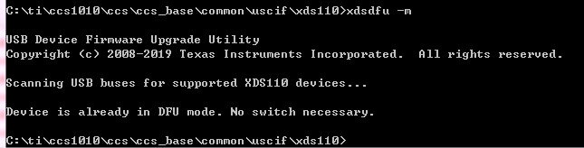
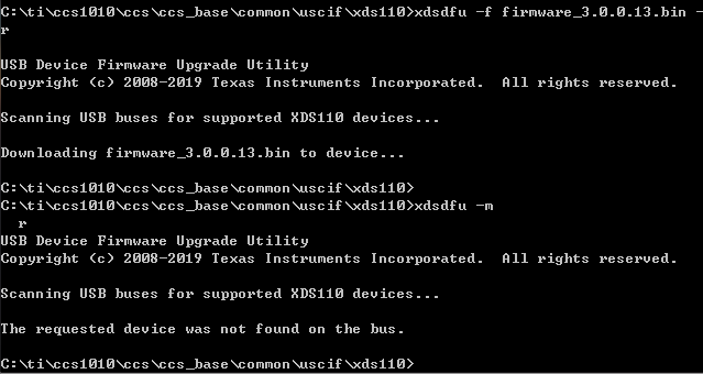
and then, use xdsdfu.exe to program firmware_3.0.0.13.bin

regards,

Jo

  • What do you mean "it is not TM4C129?" I would suggest you to check your if the connection between XDS110 and CC1352P or MSP432E401Y is secure.

  • Yikai,

    there're two version of XDS110: legacy one is TM4C129, another is MSP432E4. My customer is a dev kit maker, they followed new TI evm BOM and mount MSP432E4 on their custom CC1352 board, and program MSP432 with XDS110 firmware but didn't work. 

  • Sorry for misunderstand your issue. I am not aware that there is MSP432E4 XDS110 version. For this topic, I cannot help further and hope you can get help soon from your colleagues.

  • Hi Jo

    The software should work perfectly well on both the TM4C129 and the MSP432E4. After you have flashed the bootloader, are you able to see the device if you run "xdsdfu.exe -e" ?

    When you say it doesn't work properly. How does it work, are you able to see it in device manager after flashing the firmware?

    Vegard

  • Hi Vegard,

    Yes, I can see the device after programming bootloader when running "xdsdfu.exe -e"

    But, After programming firmware_3.0.0.13.bin the Windows device manager no longer can enumerate or recognize the USB device. I would like to check the procedure that I went through:

    1. program MSP432E4 bootloader.bin via Uniflash.

    2. reboot the chip and run xdsdfu to download firmware.bin

    Is it correct?

    thanks, 

    Jo

  • Hi.

    Yes, that is the correct procedure. To program the debugger, are you using the TagConnect connector on the backside of the board?

    Vegard

  • Hi Vegard,

    I think I was wrong about the previous result. I didn't see the device in Windows device manager after I programmed the boot_loader.bin

    I have tried two ways to download the bootloader, JTAG + Uniflash or stellaris USB DFU mode. And I found that the first word of Flash is always 0x0 no matter which programming scheme. It is not normal as the first word stores the address of reset vector of M4. the data 0x0 meaning the programming is not successful.

    So my question is, is the images for both Tiva & MSP432E4?

  • Yes, the image is for both the TIVA and the MSP device. Are you able to share the schematic of the XDS and USB chip? Have you based the design on the CC1352P launchpad?

    Vegard

  • Hi Vegard

    Yes, We developed it based on LAUNCHXL-CC1352P-2 Design Files (Rev. A)_swrc350a.

    We use the MPS432E401Y + USB3300 platform and there is no XDS110 device on the PC.

    The bootloader can complete the burning, but it fails after burning the firmware.

    After the firmware is burned, even the bootloader fails and must be burned bootload again.

    We tried every possible method but failed.

    Please help check the following steps:

    1. Use UniFlash tool JTAG interface to burn boot_loader.bin

    Please refer to the following picture.

    2. After burning the bootloader execute the following commands in cmd.exe

    xdsdfu.exe –e

    xdsdfu.exe –m

    xdsdfu.exe -f firmware_3.0.0.13.bin –r

    Please refer to the following picture.

    Please refer to this is our schematic.

    wl7152pt_evb_tb v00_sch_20200611_MSP432E401Y.pdf

    Thanks

    Ian

  • Hi, Sir

    Continue Ian's description

    We use only TM4C129NCPDT without USB3300 to work normally. This is on the previous circuit board. Using MSP432E401Y for replacement on the same circuit board can also work normally.We re-developed the circuit board based on LAUNCHXL-CC1352P-2 Design Files (Rev. A), but can't work in the same environment and operating procedures.

    bootloader burning is complete

    xdsdfu -m

    xdsdfu -f firmware_3.0.0.13.bin -r

    After the firmware is burned, execute xdsdfu -m and no bus can be found.

    We need to solve this problem in the shortest time. So very sincerely please help tell us what's wrong.

    Thanks

    Ander

  • Hi, Sir

    We continue to test possible ways and the result is failure.

    Follow the XDS110SupportReadMe.pdf command also failed.

    We have been waiting for many days in the production line.

    Please help us as soon as possible

    Thanks

    Ander

  • Hi Ander

    I am still looking into this, hold on. 

    Vegard

  • Hi, Sir

    Is there any updated information?

    Our customers are also concerned about this issue.

    We just got the LAUNCHXL pad of CC1352P, and the FW version is 02.03.00.18. Even using this version of FW still fails.

    Please confirm as soon as possible.

    Thanks

    Ander

  • Hello Vegard,

    Just a kindly reminder. We need your early feedback for this issue. Our customer is waiting for the solution.

    Thanks

    Ander

  • Hi, sorry for the delay

    To make sure I understand the case correctly. Is this correct?

    On the new device, a MSP432E401Y is mounted. This device is programmed with the boot_loader.bin file found in the XDS folder by using the JTAG interface on the MSP432 chip. When the bootloader is programmed the device shows up in device manager as  "Stellaris Device Firmware Upgrade". By using the XDSDFU utility to flash the firmware_3.0.0.xx.bin the device stops to show up anywhere. 

    And the device is fitted with a USB3300 chip between the USB port and the MSP432? If you do a flash erase of the MSP chip and ground the TDO pin of the device, does it show up in the device manager?

    Vegard

  • After looking over the schematic, I think that the whole circuit around the USB3300 chip can be removed. Since the MSP432E401 chip does not interface with anything related to the Energy trace, there is no need for high speed USB. See the debugger on the LAUNCHXL-CC1310 on how this can be done. For the launchpads with integrated Energy Trace there was a need for a higher speed USB to be able to transfer the data from ET. 

    If the USB_DP, USB_DM and USB_ID is connected to the respective pins on the MSP device you will also be able to program the device by shorting the TDO pin at boot, to force it into ROM bootloader. This will make programming of the device easier.

    Vegard

  • Yes, your understanding is correct. After F/W refreshed, it stopped and no any display. Even operated TDO, still failed.

    The circuit board fitted with USB3300 + MSP432E401Y has been made. Of course, we can re-design to remove USB3300, but NOW our production line is waiting for the solution to fix the board with USB3300+ MSP432 urgently Your response is really no help for us at this moment. Please kindly understand it.

    The circuit board we referred from LAUNCHXL pad of CC1352P and LAUNCHXL pad of CC1352P developing board , both of them were built-in with USB3300, but it works functionally. Since so , our circuit board should be workable. That’s why we are wondering if the F/W is separate. Meanwhile, we can see from the E2E discussion that USB3300 + MSP432 solution is workable. Therefore , we need your support to double confirm.

    Attached is the circuit diagram we referred for your reference.LAUNCHXL-CC1352P-2_SCHEMATIC.pdf

    Thanks
    Ander

  • I understand. 

    I can confirm that the MSP device and the TIVA device should both work with the same firmware image.

    When looking over the schematic and thinking about what can cause this, i can see that the R75 resistor got a value in your design. Is this resistor mounted?
    I tried some different scenarios with a MSP device, and with this resistor mounted. Since this pin can be driven from the JTAG header when programming the device, when the device is power cycled it can be pulled down and the device will be unable to boot. 

    If this resistor is not mounted, can you measure the voltage of the reset pin both before programming the image and after, when it isn't working.

    Vegard

  • The R75 resistor is not mounted in the circuit board. When we measured nRSTrst of MSP432 via scope , it always kept at “HIGH” from initial bootloader upgraded to last F/W refreshed.

    We tried some cross-verifications on nRST no matter in HI or LOW , the issue still can’t be fixed.

    Please kindly support to clarify shortly.

    Thanks

    Ander

  • Hi Ander. 

    I am in talks with the team that develops the XDS110 firmware, but there still haven't been a resolution from their end, hold on. 

    Vegard

  • Hi Ander. 

    We are trying to figure out if the problem is in the XDSDFU utility. 

    Can you try to program the bootloader and the firmware both from uniflash? Start the firmware at address 0x4000, like in this picture:

    Vegard

  • Hi, Vegard

    We had tested the firmware starting from the address at 0x1000 and 0xf000 previously, but failed. This time , we tested it at 0x4000 based on your suggestion, but still failed. Meanwhile, we had tried many address , but didn’t work. Please kindly support to figure out early.

    Thanks

    Ander

  • Hi Ander. 

    I am going to send you a modified version of XDSDFU with more logging capabilities, Accept my friend request here on E2E and I can send it. 

    Vegard