This thread has been locked.

If you have a related question, please click the "Ask a related question" button in the top right corner. The newly created question will be automatically linked to this question.

CC1310: RF range and board impedence issu

Part Number: CC1310

Hi All,

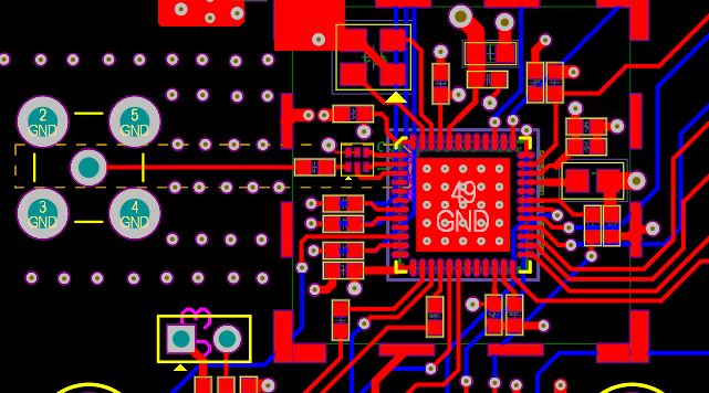
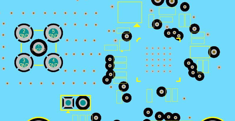
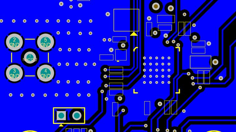
We designed and developed a project using CC1310. In this project, we built custom boards as per the CC1310 with help from Application Report SWRA524A. The boards are 4-layer impedance controlled boards. Pictures of schematics, layout, board stackup and component list are attached.

On testing of these custom boards (one used as transmitter and another one as receiver) we are not getting expected range for communication. We require range of about 400 to 500 meters in outdoor application (Line of Sight), but we are getting the range around 75 meters only. Our RF bit rate is about 50Kbps.

We analyzed  the boards on Network Analyzer and observed that VSWR and return loss are not good for our working frequency band which is 865 to 867 MHz. For this frequency band we are getting the VSWR around 4.8, which is way too high. VSWR was below 2 for frequency range of 1.102 GHz to 1.152 GHz. The dip was at frequency of around 1.13 GHz where VSWR was below 1.5. The return loss also showed a dip at that frequency (-20 dB), whereas it was high for 865 to 867 MHz (-4bB). Pictures for VSWR and return loss are attached.

Kindly let us know if we have done anything wrong with the schematics, components or layout. Please provide suggestions to resolve this issue and get good VSWR and Return loss numbers for frequency band of 865-867 MHz, so that it improves the communication range to exceed our expectations.

Thank you.

Kashif 

     Component list.xlsx

  • Hello,


    Thanks for your response.


    During the testing (that we mentioned above), we had not connected the antenna. The rubber duck antenna was removed from the antenna SMA connector of the board. The board was not powered. The Network Analyzer cable was connected to the antenna SMA connector on the board. With this setup, the readings were taken. So it appears that the issue is on the board. Can you please suggest some resolution?


    Thanks,

    Kashif

  • Hi,

    I would put the radio into a static Rx mode, whilst measuring with the VNA.

    Regards,

       Richard

  • Thanks Richard.

    I will try putting the radio in static Rx mode and take readings again.

    But we are getting a practical outdoor Line of Sight range of only about 75 meters. Can you please review our schematics, layout and stackup and let us know if we are doing some obvious mistakes? I think we should easily get range of more than 500 mtrs that we are targeting. Kindly guide us on what needs to be corrected to get proper communication range.

    Thanks and regards,

    Kashif

  • Hello Richard.

    Can you please elaborate on "I would put the radio into a static Rx mode, whilst measuring with the VNA."?

    Thanks & Regards,

    Kashif Khan.

  • Hi,

    When the radio is entered into static Rx mode, then you should see roughly 50 ohm impedance. 

    What is the conducted output power level you are measuring ?

    Regards,

       Richard

  • Hi,

    Need to confirm that the conducted performance is adequate first. When this has been confirmed that this looks good, then we can review the antenna.

    Regards,

       Richard

  • Hello Richard,

    The test results with the VNA which we had shared earlier were for conducted performance (VNA port connected to SMA connector of board).

    The conducted power level we are measuring is -7.6 dbm (CC1310 is configured for 13 dbm output power).  Lot of spurious emissions are also seen outside the channel band. Please see attached picture1 of result on the spectrum analyser. Sometimes the channel envelope is not symmetrical (see picture2).

    Also, did you get a chance to check the schematics and layout files?


    Thanks,

    Kashif

  • HI,

    Losing around 20 dB here...

    Make sure the IPC is in the right direction or not damaged. 

    Do you see this on several boards / IPCs ?

    Regards,

       Richard

  • For debugging purposes:

    • Set the radio into a static_tx mode without any modulation
      • Measure output power
    • Use the SmartRF studio to control your board just so we know the software is OK for now.

    //Richard

  • Hi Richard,

       We have checked IPC on several boards and found it's in the right direction also not damaged. As per your suggestion, we tested the radio into static Tx mode without modulation using a Smart RF studio. We set the Tx power at -10 dBm and observed -13.0 dBm on the Spectrum analyzer. In the second reading observed -9.5 dBm on SA at 0 dBm Tx power.    

    Regards,

    Kashif

  • Hi Richard,

    Do you want us to do any other debugging?

    Also, did you find anything wrong with schematics, layout, or PCB stackup?

    Thanks,

    Kashif

  • Hi,

    The schematic looks OK but the layout does not look optimum.

    The top layer is *.GTL. Is *.G1 directly underneath the top layer. Then *.G2 and finally *.GBL at the bottom.

    *.G1 looks like a "solid" GND layer but do not understand why the power plane *.G2 has been opened up underneath the RF.

    Confirm which layer is underneath the top layer.

    Regards,

       Richard

  • Hi Richard,

    Thank you for your reply.

    The layer order is GTL (top) followed by G1 (Ground) followed by G2 (Power) followed by GBL (Bottom).

    Power islands for VDDR, VDDS etc are implemented in G2 plane. Does G2 plane need to be changed?

    Could problems in layout be the root cause of the issue we are seeing?

    We have used IPC in this design (Johanson). Is this good or using the discrete solution for Balun, filter be a good idea?

    Discrete solution may help if tuning for frequency is required. Is that so?

    Our frequency range is 865 to 867 MHz (not 868 MHz). Will this cause a problem?

    Our PCB stackup is different than the evaluation module layout. But we had designed as per 50 ohms impedance controlled PCB. Will this cause a problem?

    We are still confused as to what would be causing such a large loss of output power.

    Thanks,

    Kashif

  • Hi Kashif,

    Closing this thread and continue the debugging via email.

    Regards,

       Richard