This thread has been locked.

If you have a related question, please click the "Ask a related question" button in the top right corner. The newly created question will be automatically linked to this question.

CCS/CC1312R: I2S driver architecture with only one buffer

Part Number: CC1312R
Other Parts Discussed in Thread: CC1310,

Tool/software: Code Composer Studio

Short version: Is it possible to use the I2S driver with a single buffer?

Longer version: I have the following traffic:

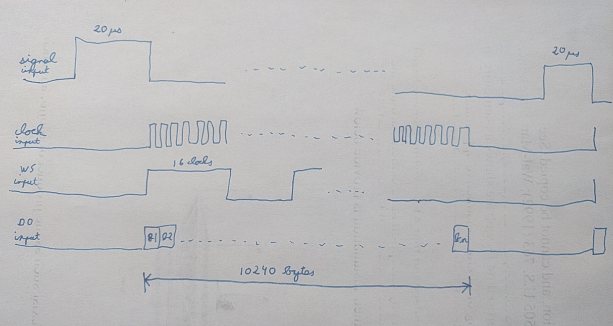
I have the following reserved memory:

unsigned char mybuffer[10240];

I have a callback on the posedge of the SIGNAL interrupt and in this callback there are two options:

- either I want to "record" and store the coming 10240 bytes in mybuffer.

- or I don't want to do anything and mybuffer should not be touched.

I would like to avoid any memcpy, to have the minimum of interrupts/callbacks possible and to set fixedBufferLength to 10240.

Question 1: Is it better to stop/start the I2S (with the API I2S_stopClocks(handle); I2S_startClocks(i2sHandle); I2S_startRead(i2sHandle);) or is it better to have it running all the time? (Note that the I2S driver in SLAVE mode).

Question 2: Can I have one single buffer and how to manage it in readCallbackFxn?

Note that I "own" the clock, WS and D0 lanes from a FPGA (for instance, I could have a free-running clock).

  • Hi Gregoire,

    What version of the SimpleLink CC13x2/26x2 SDK are you using?

    Can you please specify what you mean by "I want to record and store"? 

    Please let us get back to you on your two questions.

  • My final hardware will be cc1312R but I'm currently experimenting on cc1310. I'm using cc13x0_sdk_4_10_01_01. For some reasons, my traffic is now in DSP mode, not in I2S mode. I have spent a lot of time on this :-( and I found multiple bugs / problems for DSP mode in I2SCC26XX.c. Also, the datasheet is incorrect: for instance figure 22.7 of cc1310-tr: MSB is not at the same time of WS, it's after. It's the whole problem of the driver which doesn't take into account the additional WS clock cycle for DSP. I have made work DSP output with some patches (I don't use output) but input still doesn't work.

  • I'm facing two problems:

    - bug/problem to get the correct frame in memory in DSP mode.

    - an architecture challenge. When I'm about to receive some I2S traffic, my software decides if data should be stored in memory or if it should be ignored. Because I have only one memory buffer which is very large (>10kB), I cannot afford to have two buffers and receive the traffic in the second buffer to virtually discard it (i.e. not overwriting the first buffer). The solution is probably to use stop/startReads but I was not able to make this work reliably. In any case, I'm currently stopped by the first problem mentioned above.

  • Hi Gregoire,

    - the issue you are mentioning with the DSP mode seems to be already have been discussed here. Our R&D team is in the process to implement the fix.

    - because of the way the I2S module is made, you cannot start an I2S operation with only one buffer. You could chose to have two buffers twice smaller or modify the I2S driver (this could work only because you have a very big buffer).

    Looking at your draws one more time, I don't think you should call I2S_stopClocks() in between the transmissions (because you expect to sample on the very first WS cycle).

    Let me know if you have more questions,

    Regards,

  • I really need a fix on this sub-problem #1 I describe above. I have spent more than a week full time on this integration thinking the problem was on my FPGA code, and the problem is on the TI driver side (even perhaps on hardware or in the datasheet).

    Your patch ONLY fixes the problem for output. It DOES NOT work for input in DSP / slave.

    - with the patch mentioned in the other thread, for a 16-bit transfer, you have 16 clock cycles between each WS including the WS. So the MSB happens at the same time than WS. It's not what the datasheet says. But it's fine. I'm interested only by input, output for me is just to understand how hardware is working.

    - with the code I sent you, for a 16-bit transfer, you have 17 clock cycles: the WS and then the 16-bit transfer. MSB happens after WS. This is what the datasheet says.

    - with your patch for input in DSP / slave, IT'S NOT WORKING. And both if my FPGA outputs 16 or 17 clocks.

    To help move forward, can you please provide a working example of input DSP/slave by connecting two launchpads, one in DSP/master (with your patch or with my modification), the other in DSP/input.

  • The captures in my previous post are for a 0x88 traffic.

  •  Datasheet on paragraph 22.6.4 says:

    "Figure 22-7 shows the DSP interface format. DSP is a single-phase format, I2S:AIFFMTCFG.DUAL_PHASE = 0, where WCLK is high for one BCLK period, followed by each audio channel back-to-back. Data is sampled on the falling edge of BCLK and updated on the rising edge of BCLK; this is configured by setting I2S:AIFFMTCFG.SMPL_EDGE = 0. There is an optional IDLE period at the end of the clock phase between the last data channel and the next WCLK period; logical 0 is output during this period. The number of BCLK cycles in the phase must be equal to or higher than the word length, as specified in the I2S:AIFFMTCFG.WORD_LEN register, times
    the number of specified channels (determined by the most significant 1 in all the I2S:AIFWMASKn registers combined)."

    In output mode, your patch (which makes things working) is not compliant with what the datasheet says. Anyway, I'm only interested by input.

  • With my modification for output, the MSB bit is duplicated during the WS cycle.

    For input, it doesn't work.

  • In input mode, with your patch, 0x88 traffic is not recognized at all because hardware sees that one bit is missing so the transaction is never completed. It also proves that hardware wants 17 cycles for 16 bit in DSP (WS+data). With my modification, the traffic appears as 0x44 which makes me believe there is a bug in hardware (I hope I'm wrong - usually I'm wrong when I'm blaming hardware!).

  • Can someone at TI please at least acknowledge my problem, i.e. the chip and the I2S driver cannot recognize I2S DSP traffic in slave mode?

  • Hi,

    Do you have the same observations for CC1310 and CC1312?

    Are you now using the I2S driver, the I2S driverlib or directly writing to the registers?

    Regards,

  • I'm tired of this situation because I have spent 10 days full time on this and nothing is done on the TI side. I'm wasting time.

    EVERYTHING POINTS NOW TO A HARDWARE ISSUE. I hope I'm wrong. I really hope that it's either a TI driver bug or an application software issue. But I don't think it's the case.

    In slave mode (clock and WS provided by external), for a DSP traffic, the bit count is not correct resulting in corrupted data in memory.

    I have given TI everything to reproduce the bug. CONFIRM IT or provide the registers settings to make work DSP/slave (I really prefer that second option).

    This is with cc1310. I might test for cc1312 after reception of some new hardware but you need to understand that I'm not the QA employee of TI... This configuration is officially supported by the TI driver and it hasn't been tested.

    What is the procedure to escalate this issue to some high-level managers?

  • Additionally, a case has been opened in the TI system: CS0276397

  • Hi Gregoire,

    I understand your frustration and I am doing my best to help you. An internal ticket is currently opened and the R&D team will address it.

    To help the process, please provide the code examples you mentioned here.

    Thanks and regards,