


I am working with the CC1101 and using the examples posted by TI. I am using the Link2 example and I have modified it a little to suit my needs. I am trying to program the board to read data from the UART and transmit that data. I am able to send the data correctly on the first packet sent, but as I send subsequent packets, the rxBuffer does not receive the values correctly.
Here is my transmitter code:
TX
//-------------------------------------------------------------------------------------------------------
// Global Variables
BYTE xdata buffer[8];
BYTE xdata txBuffer[258];
UINT8 state = SETUP;
// Byte array used by the intToAscii(UINT16 value) function
UINT8 xdata asciiString[6];
TX_DATA xdata txData = {
0, // bytesLeft
0, // iterations
FALSE, // writeRemainingDataFlag
FALSE, // packetSentFlag
txBuffer, // *pBufferIndex
0 // packetsSent
};
// PKT_DATA xdata pktData;
//-------------------------------------------------------------------------------------------------------
void main (void) {
// BYTE xdata menuEntry;
// UINT16 packetsSent = 0;
// UINT8 length;
UINT16 xdata i;
UINT16 xdata numberOfPackets = 1;
// UINT16 xdata k;
// UINT8 regCounter;
#ifdef STAND_ALONE
// Select the Internal Oscillator as Multiplier input source and disable the watchdog timer
// SYSCLK = 4X Clock Multiplier / 2
CLOCK_INIT();
#endif
// Set up the crossbar and I/O ports to communicate with the SmartRF04EB peripherals
IO_PORT_INIT();
// Initialize the LCD display. The SMBus uses timer 0 to generate SCL
ebLcdInit();
// Initialize the ADC converter
ebAdcInit(ADC_JOY);
// 8-bit Uart with variable baudrate, logic level of stop bit is ignored. User must poll the
// RI_0 and TI_0 flag to determine when a byte arrives or when the TX buffer is empty.
// Timer1 is used as a baudrate generator
halUartSetup(UART_BAUDRATE_115200, DEFAULT_MODE);
SPI_INIT(SCLK_6_MHZ);
// halUartSetup(UART_BAUDRATE_115200, DEFAULT_MODE);
POWER_UP_RESET_CCxxx0();
halRfWriteRfSettings(&rfSettings);
//halSpiWriteReg(CCxxx0_FIFOTHR, 0x0E); // FIFO_THR = 14
// 5 bytes in TX FIFO (59 available spaces)
// 60 bytes in the RX FIFO
// If this threshold is changed, AVAILABLE_BYTES_IN_TX_FIFO
// and BYTES_RX_FIFO (Link2.h) must be updated
//halSpiWriteReg(CCxxx0_IOCFG1,0x2E); // GDO1 output pin configuration
halSpiWriteReg(CCxxx0_SYNC1,0x54); // SYNC1 Sync Word, High Byte
halSpiWriteReg(CCxxx0_SYNC0,0xD5); // SYNC0 Sync Word, Low Byte
//halSpiWriteReg(CCxxx0_CHANNR,0x00); // Channel number
//halSpiWriteReg(CCxxx0_MCSM2,0x00); // Main Radio Control State Machine configuration
//halSpiWriteReg(CCxxx0_MCSM1,0x30); // Main Radio Control State Machine configuration
halSpiWriteReg(CCxxx0_WOREVT1,0x87); // WOREVT1 Time out high byte event0
halSpiWriteReg(CCxxx0_WOREVT0,0x6B); // WOREVT0 Time out low byte event0
halSpiWriteReg(CCxxx0_WORCTRL,0xFB); // WORCTRL Wake On Radio Control
//halSpiWriteReg(CCxxx0_RCCTRL1,0x1F); // RCCTRL0 RC Oscillator Configuration
//halSpiWriteReg(CCxxx0_RCCTRL0,0x1F); // RCCTRL0 RC Oscillator Configuration
halSpiWriteReg(CCxxx0_PATABLE, paTable[0]);
UART_RX_ENABLE();
INT_PRIORITY(INUM_EXTERNAL1, INT_HIGH);
ebLcdUpdate("Mode: TX", "Push S1 to Start");
// Infinite loop
while (TRUE) {
// Create data packet
switch (state)
{
case SETUP:
// This wait is implemented to give the LCD display enough time to be update
// between each iteration
halWait(250);
if (ebButtonPushed())
{
//ENABLE_GLOBAL_INT(INT_OFF);
printf("Hello World\n");
state = TX_START;
// Associated to the TX FIFO: Asserts when the TX FIFO is filled above TXFIFO_THR.
// De-asserts when the TX FIFO is below TXFIFO_THR.
halSpiWriteReg(CCxxx0_IOCFG2, 0x02);
SETUP_GDO2_INT(EDGE, LOW); // Enables external interrupt on falling edge
SETUP_GDO0_INT(EDGE, LOW);
ebLcdUpdate("Button pushed", "Waiting for data");
}
_nop_(); // If this instruction is removed, IE0 might not be cleared
INT_SETFLAG(INUM_EXTERNAL0, INT_CLR); // Clears the interrupt flag
INT_SETFLAG(INUM_EXTERNAL1, INT_CLR); // Clears the interrupt flag
ENABLE_GLOBAL_INT(INT_ON);
break;
case TX_START:
// Create data packet
createDataPacket();
// The TX FIFO needs to be re-filled several times
halSpiWriteBurstReg(CCxxx0_TXFIFO, txBuffer, FIFO_SIZE); // Fill up the TX FIFO
halSpiStrobe(CCxxx0_STX);
for(i = 1; i <= 101; i++)
{
printf ("TX %u: %X\n", i, txBuffer[i]);
}
txData.bytesLeft = 101 + 1 - FIFO_SIZE;
txData.pBufferIndex = txBuffer + FIFO_SIZE;
txData.iterations = (txData.bytesLeft / AVAILABLE_BYTES_IN_TX_FIFO);
if (!txData.iterations)
txData.writeRemainingDataFlag = TRUE;
// Enable external interrupt 1 (the TX FIFO will need to be re-filled in this ISR)
ENABLE_GLOBAL_INT(INT_OFF);
INT_ENABLE(INUM_EXTERNAL1, INT_ON);
INT_SETFLAG(INUM_EXTERNAL1, INT_CLR);
ENABLE_GLOBAL_INT(INT_ON);
state = TX_WAIT;
//----------------------------------------------------------------------------------------
case TX_WAIT:
//----------------------------------------------------------------------------------------
if (txData.packetSentFlag)
{
txData.packetSentFlag = FALSE;
intToAscii(++txData.packetsSent);
// ebLcdUpdate("Sent:", asciiString);
if (txData.packetsSent < numberOfPackets)
state = TX_START;
else
{
for(i = 1; i <= 101; i++)
{
printf ("TX %u: %X\n", i, txBuffer[i]);
}
halWait(1000000);
txData.packetsSent = 0;
state = SETUP;
ebLcdUpdate("Packets Sent", "S1 to restart");
}
}
break;
//----------------------------------------------------------------------------------------
default:
//----------------------------------------------------------------------------------------
break;
}
}
}
// void createDataPacket(UINT 16)
//
// DESCRIPTION:
// This function is called before a packet is going to be transmitted.
// Packet format:
//
// |----------------------------------------------------------------------------------------------------
// | | | | | | | |
// | Length field | Address Field | Data | Data |............| Data | Data |
// | | | | | | | |
// |----------------------------------------------------------------------------------------------------
// ^ ^ ^ ^
// | | | |
// txBuffer[0] txBuffer[1] txBuffer[2] txBuffer[menuData.packetLength]
//-------------------------------------------------------------------------------------------------------
void createDataPacket(void)
{
UINT16 mm;
txBuffer[0] = ADDR;
for (mm = 1; mm <= 101; mm++)
{
if(mm == 1)
txBuffer[mm] = 0x66;
// UART_WAIT_AND_RECEIVE(txBuffer[i]);
else
txBuffer[mm] = 0x01;//rand();
}
// printf("Done and done");
//}
} //createDataPacket
//-------------------------------------------------------------------------------------------------------
// void EXTERNAL1_ISR(void)
//
// DESCRIPTION:
// This ISR is only enabled when the length byte is 64 or greater in TX or 62 or greater in RX.
// In TX mode there will be an interrupt when the number of bytes in the TX FIFO goes below the threshold
// (less than 5 bytes left in the TX FIFO) and in RX mode there will be an interrupt when there are
// 60 bytes in the RX FIFO.
// For better understanding on how this interrupt work, please see the
// CC1100/CC1150DK & CC2500/CC2550DK Development Kit Examples and Libraries User Manual
//-------------------------------------------------------------------------------------------------------
void EXTERNAL1_ISR(void) interrupt INUM_EXTERNAL1 {
//----------------------- TX MODE -----------------------
if (txData.writeRemainingDataFlag) { // Less than 60 bytes to write to the TX FIFO
halSpiWriteBurstReg(CCxxx0_TXFIFO, txData.pBufferIndex, txData.bytesLeft);
INT_ENABLE(INUM_EXTERNAL1, INT_OFF);
} else {
halSpiWriteBurstReg(CCxxx0_TXFIFO, txData.pBufferIndex, AVAILABLE_BYTES_IN_TX_FIFO);
txData.pBufferIndex += AVAILABLE_BYTES_IN_TX_FIFO;
txData.bytesLeft -= AVAILABLE_BYTES_IN_TX_FIFO;
if (!(--txData.iterations))
txData.writeRemainingDataFlag = TRUE;
}
//-------------------------------------------------------
IE1 = 0; // Clear the interrupt flag in case the interrupt flag were set while in the ISR
}// EXTERNAL_ISR
//-------------------------------------------------------------------------------------------------------
// void EXTERNAL0_ISR(void)
//
// DESCRIPTION:
// In TX mode, this ISR will run when a packet has been sent. In RX mode it will run both when sync
// is received (rising edge) and when the whole packet is received (falling edge).
// For better understanding on how this interrupt work, please see the
// CC1100/CC1150DK & CC2500/CC2550DK Development Kit Examples and Libraries User Manual
//-------------------------------------------------------------------------------------------------------
void EXTERNAL0_ISR(void) interrupt INUM_EXTERNAL0
{
txData.writeRemainingDataFlag = FALSE;
txData.packetSentFlag = TRUE;
}
// EXTERNAL_ISR
//-------------------------------------------------------------------------------------------------------
// void intToAscii(UINT32 value)
//
// DESCRIPTION:
// Takes a 32 bits interger as input and converts it to ascii. Puts the result in the global
// variable asciiString[]
//
// ARGUMENTS:
// UINT32 value
// The value to be converted
//-------------------------------------------------------------------------------------------------------
void intToAscii(UINT16 value)
{
UINT8 i;
UINT8 j = 0;
UINT8 digit_start = 0;
UINT16 digit = 0;
UINT32 denom = 1000000000;
if (value == 0)
{
asciiString[0] = '0';
asciiString[1] = NULL;
}
else
{
for(i = 10; i > 0; i--)
{
digit = value / denom;
if((digit_start == 1) || (digit != 0))
{
digit_start = 1;
value %= denom;
asciiString[j++] = (digit + '0');
}
denom /= 10;
}
asciiString[j++] = NULL;
}
}// intToAscii
Here is my receiver code:
RX
BYTE xdata buffer[8];
BYTE xdata rxBuffer[258];
UINT8 xdata state = SETUP;
// Byte array used by the intToAscii(UINT16 value) function
UINT8 xdata asciiString[6];
RX_DATA xdata rxData = {
0, // bytesLeft
FALSE, // packetReceivedFlag
SYNC, // syncOrEndOfPacket
rxBuffer, // *pBufferIndex
0, // lengthByte
FALSE, // crcOK
0 // packetsReceived
};
//-------------------------------------------------------------------------------------------------------
void main (void) {
UINT8 xdata numberOfPackets = 1;
UINT8 xdata arr_size = 100;
UINT16 xdata k;
// UINT8 regCounter;
#ifdef STAND_ALONE
// Select the Internal Oscillator as Multiplier input source and disable the watchdog timer
// SYSCLK = 4X Clock Multiplier / 2
CLOCK_INIT();
#endif
// Set up the crossbar and I/O ports to communicate with the SmartRF04EB peripherals
IO_PORT_INIT();
// Initialize the LCD display. The SMBus uses timer 0 to generate SCL
ebLcdInit();
// Initialize the ADC converter
ebAdcInit(ADC_JOY);
// 8-bit Uart with variable baudrate, logic level of stop bit is ignored. User must poll the
// RI_0 and TI_0 flag to determine when a byte arrives or when the TX buffer is empty.
// Timer1 is used as a baudrate generator
halUartSetup(UART_BAUDRATE_115200, DEFAULT_MODE);
SPI_INIT(SCLK_6_MHZ);
POWER_UP_RESET_CCxxx0();
halRfWriteRfSettings(&rfSettings);
// Changed (ok)
halSpiWriteReg(CCxxx0_SYNC1,0x54); // SYNC1 Sync Word, High Byte
halSpiWriteReg(CCxxx0_SYNC0,0xD5); // SYNC0 Sync Word, Low Byte
halSpiWriteReg(CCxxx0_CHANNR,0x00); // Channel number
halSpiWriteReg(CCxxx0_MCSM2,0x00); // Main Radio Control State Machine configuration
halSpiWriteReg(CCxxx0_MCSM1,0x30); // Main Radio Control State Machine configuration
halSpiWriteReg(CCxxx0_WOREVT1,0x87); // WOREVT1 Time out high byte event0
halSpiWriteReg(CCxxx0_WOREVT0,0x6B); // WOREVT0 Time out low byte event0
halSpiWriteReg(CCxxx0_WORCTRL,0xF8); // WORCTRL Wake On Radio Control
halSpiWriteReg(CCxxx0_FSCAL0,0x1F); // Frequency synthesizer calibration
halSpiWriteReg(CCxxx0_RCCTRL1,0x1F); // RCCTRL0 RC Oscillator Configuration
halSpiWriteReg(CCxxx0_RCCTRL0,0x1F); // RCCTRL0 RC Oscillator Configuration
halSpiWriteReg(CCxxx0_PATABLE, paTable[0]);
ebLcdUpdate("Mode: Rx", "Push S1 To Rec");
// Enable the UART receiver
UART_RX_ENABLE();
INT_PRIORITY(INUM_EXTERNAL1, INT_HIGH);
// Infinite loop
while (TRUE) {
switch (state) {
//----------------------------------------------------------------------------------------
case SETUP:
//----------------------------------------------------------------------------------------
// This wait is implemented to give the LCD display enought time to be update
// between each iteration
halWait(250);
if (ebButtonPushed())
{
ENABLE_GLOBAL_INT(INT_OFF);
state = RX_START;
ebLcdUpdate("Waiting for", "data");
// Associated to the RX FIFO: Asserts when RX FIFO is filled above RXFIFO_THR.
// De-asserts when RX FIFO is drained below RXFIFO_THR.
halSpiWriteReg(CCxxx0_IOCFG2, 0x00);
SETUP_GDO2_INT(EDGE, HIGH); // Enables external interrupt on rising edge
SETUP_GDO0_INT(EDGE, HIGH);
_nop_(); // If this instruction is removed, IE0 might not be cleared
INT_SETFLAG(INUM_EXTERNAL0, INT_CLR); // Clears the interrupt flag
INT_SETFLAG(INUM_EXTERNAL1, INT_CLR); // Clears the interrupt flag
ENABLE_GLOBAL_INT(INT_ON);
}
break;
//----------------------------------------------------------------------------------------
case RX_START:
//----------------------------------------------------------------------------------------
halSpiStrobe(CCxxx0_SRX);
state = RX_WAIT;
//----------------------------------------------------------------------------------------
case RX_WAIT:
//----------------------------------------------------------------------------------------
if (rxData.packetReceivedFlag)
{
rxData.packetReceivedFlag = FALSE;
rxData.pBufferIndex = rxBuffer;
if (rxData.crcOK)
{
for(k = 0; k < rxData.lengthByte; k++)
printf("\nReceived %u = %X",k,rxBuffer[k]);
ebLcdUpdate("Packet Received", "Push S1 to receive again");
state = SETUP;
halWait(10000);
}
state = RX_START;
// Enable external interrupt 1 in case the packet length is greater than 61 bytes.
// Configure external interrupt 0 to give an interrupt on rising edge (sync received)
ENABLE_GLOBAL_INT(INT_OFF);
INT_ENABLE(INUM_EXTERNAL1, INT_ON);
_nop_(); // If this instruction is removed, IE1 might not be cleared
INT_SETFLAG(INUM_EXTERNAL1, INT_CLR);
SETUP_GDO0_INT(EDGE, HIGH);
_nop_(); // If this instruction is removed, IE0 might not be cleared
INT_SETFLAG(INUM_EXTERNAL0, INT_CLR);
ENABLE_GLOBAL_INT(INT_ON);
}
break;
//----------------------------------------------------------------------------------------
default:
//----------------------------------------------------------------------------------------
break;
}
}
}
//-------------------------------------------------------------------------------------------------------
// void EXTERNAL1_ISR(void)
//
// DESCRIPTION:
// This ISR is only enabled when the length byte is 64 or greater in TX or 62 or greater in RX.
// In TX mode there will be an interrupt when the number of bytes in the TX FIFO goes below the threshold
// (less than 5 bytes left in the TX FIFO) and in RX mode there will be an interrupt when there are
// 60 bytes in the RX FIFO.
// For better understanding on how this interrupt work, please see the
// CC1100/CC1150DK & CC2500/CC2550DK Development Kit Examples and Libraries User Manual
//-------------------------------------------------------------------------------------------------------
void EXTERNAL1_ISR(void) interrupt INUM_EXTERNAL1 {
//-------------------------------------------------------
//----------------------- RX MODE -----------------------
// Do not empty the FIFO (See the CC1100 or 2500 Errata Note)
halSpiReadBurstReg(CCxxx0_RXFIFO, rxData.pBufferIndex, (BYTES_IN_RX_FIFO - 1));
rxData.bytesLeft -= (BYTES_IN_RX_FIFO - 1);
rxData.pBufferIndex += (BYTES_IN_RX_FIFO - 1);
//-------------------------------------------------------
IE1 = 0; // Clear the interrupt flag in case the interrupt flag were set while in the ISR
}// EXTERNAL_ISR
//-------------------------------------------------------------------------------------------------------
// void EXTERNAL0_ISR(void)
//
// DESCRIPTION:
// In TX mode, this ISR will run when a packet has been sent. In RX mode it will run both when sync
// is received (rising edge) and when the whole packet is received (falling edge).
// For better understanding on how this interrupt work, please see the
// CC1100/CC1150DK & CC2500/CC2550DK Development Kit Examples and Libraries User Manual
//-------------------------------------------------------------------------------------------------------
void EXTERNAL0_ISR(void) interrupt INUM_EXTERNAL0 {
if (rxData.syncOrEndOfPacket == SYNC) {
// After the sync word is received one needs to wait some time before there will be any data
// in the FIFO.In addition, the FIFO should not be emptied
// (See the CC1100 or 2500 Errata Note) before the whole packet has been
// received.
halWait(70); // Allow for 2 bytes to be put in the FIFO (2*8*(1/250000)) = 64 us
if (PACKET_INT) { // If this pin has gone low again, one can assume that the lenght byte
// was 0 (nothing was put in the RX FIFO)
rxData.lengthByte = 101;
rxData.bytesLeft = rxData.lengthByte + 2;
rxData.syncOrEndOfPacket = END_OF_PACKET;
if (rxData.bytesLeft < FIFO_SIZE)
// Disable interrupt on threshold since it is room for the whole packet in the FIFO
INT_ENABLE(INUM_EXTERNAL1, INT_OFF);
SETUP_GDO0_INT(EDGE, LOW); // Enables external interrupt on falling edge (packet received)
_nop_(); // If this instruction is removed, IE0 might not be cleared
INT_SETFLAG(INUM_EXTERNAL0, INT_CLR);
}
} else { // End of Packet
halSpiReadBurstReg(CCxxx0_RXFIFO, rxData.pBufferIndex, rxData.bytesLeft);
rxBuffer[0] = rxData.lengthByte;
rxData.syncOrEndOfPacket = SYNC;
rxData.packetReceivedFlag = TRUE;
rxData.crcOK = TRUE;
}
//-------------------------------------------------------
}// EXTERNAL_ISR
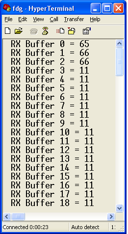
The output that I see is this on the first packet:
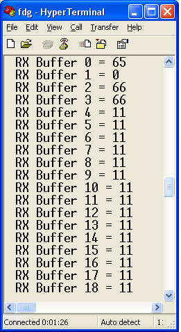
on the next packet, this is the output that I see:
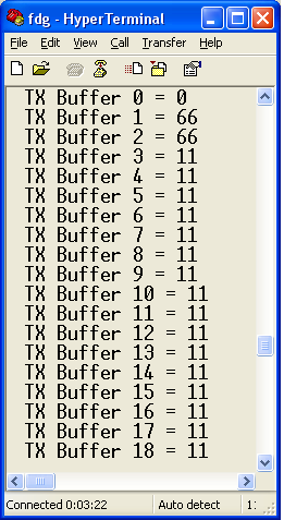
I have checked the txBuffer after the packet transmission and the packet indexing does not seem to change. This is the output that I see:
Somewhere along the line I am messing up my receive buffer indexing and I can't seem to figure it out. Has anyone encountered something similar to this?
Thanks for your help in advance.
-Jon
