This thread has been locked.

If you have a related question, please click the "Ask a related question" button in the top right corner. The newly created question will be automatically linked to this question.

CC1352R: CC1352R external flash is not working with custom board.

Part Number: CC1352R
Other Parts Discussed in Thread: SYSCONFIG

Hi,

I am using SDK CC13x2_26x2_sdk_3_30_00_03 sensor_oad _offchip_ secure example.  I tested this example with the launchpad, an external flash is working fine. 

 In Custom board we are using Mx251635FZUIL0 flash and flash is connected to IOID_20(MOSI), IOID_19(MISO), IOID_17(SPI_clk), IOID_10(CS) pins. To test with a custom board I configured SPI with these gpios

using CC1352R1_LAUNCHXL.h file. 

External flash is not working with a custom board, getting NVS_STATUS _ERROR.

Why external flash is not working with external flash??

  • - To simplify the software some, have you also tested http://dev.ti.com/tirex/explore/node?node=AOcyFNRwuFPnvZgA6DVXfg__pTTHBmu__LATEST to see if this give a different result? 

    - Could you post the part of the code you have changed?

    - Is it possible to take a screenshot of the schematic that shows the connection between the chip and the flash?

    - Have you tried to probe the SPI interface to see if some pins are toggling? 

  • Hi TER, 

    - To simplify the software some, have you also tested http://dev.ti.com/tirex/explore/node?node=AOcyFNRwuFPnvZgA6DVXfg__pTTHBmu__LATEST to see if this give a different result? 

    i have tested  with external flash example, facing same problem. NVS_write is returning -7 value.

    Could you post the part of the code you have changed?

    I changed only CC1352R1_LAUNCHXL.h file for gpio i mentioned in orange color.

    /* SPI */
    #define CC1352R1_LAUNCHXL_SPI_FLASH_CS       IOID_10//IOID_20
    #define CC1352R1_LAUNCHXL_FLASH_CS_ON        0
    #define CC1352R1_LAUNCHXL_FLASH_CS_OFF      1

    /* SPI Board */
    #define CC1352R1_LAUNCHXL_SPI0_MISO               IOID_19//IOID_8 /* RF1.20 */
    #define CC1352R1_LAUNCHXL_SPI0_MOSI               IOID_20//IOID_9 /* RF1.18 */
    #define CC1352R1_LAUNCHXL_SPI0_CLK                 IOID_17//IOID_10 /* RF1.16 */
    #define CC1352R1_LAUNCHXL_SPI0_CSN                 PIN_UNASSIGNED//IOID_11
    #define CC1352R1_LAUNCHXL_SPI1_MISO               PIN_UNASSIGNED
    #define CC1352R1_LAUNCHXL_SPI1_MOSI               PIN_UNASSIGNED
    #define CC1352R1_LAUNCHXL_SPI1_CLK                 PIN_UNASSIGNED
    #define CC1352R1_LAUNCHXL_SPI1_CSN                PIN_UNASSIGNED

    - Is it possible to take a screenshot of the schematic that shows the connection between the chip and the flash?

    yes but i can't post it here, i will post in private message


    Have you tried to probe the SPI interface to see if some pins are toggling? 

    External flash is working with  ext_flash.c files

  • - I will wait for details on the HW on a private message

    - Not sure what you mean be "External flash is working with  ext_flash.c files"? 

  • - I will wait for details on the HW on a private message

    please accept my friend request  for private message

    - Not sure what you mean be "External flash is working with  ext_flash.c files"? 

    i used following APIs for external flash. With these APIs I am able to write and from external flash

    /**
    * Initialize storage driver.
    *
    * @return True when successful.
    */
    extern bool extFlashOpen(void);

    /**
    * Close the storage driver
    */
    extern void extFlashClose(void);

    /**
    * Get flash information
    */
    extern const ExtFlashInfo_t *extFlashInfo(void);

    /**
    * Read storage content
    *
    * @return True when successful.
    */
    extern bool extFlashRead(size_t offset, size_t length, uint8_t *buf);

    /**
    * Erase storage sectors corresponding to the range.
    *
    * @return True when successful.
    */
    extern bool extFlashErase(size_t offset, size_t length);

    /**
    * Write to storage sectors.
    *
    * @return True when successful.
    */
    extern bool extFlashWrite(size_t offset, size_t length, const uint8_t *buf);


  • I'll look closer into why one API works and another causes issues. It looks like you are not using syscfg, does that mean you have disabled it? 

  • I'm using CC13x2_26x2_sdk_3_30_00_03 SDK, it doesn't have syscfg.  Today I tested with SDK4.3, same issue with new SDK also

  • 3.30 has syscfg, this was the first version it was present on. 

    But, for the test you did with SDK4.30, could you post the resulting ti_drivers_config.c file? I'm also waiting for the schematic as a PM. 

  • 3.30 has syscfg, this was the first version it was present on. 

    sorry, i used CC13x2_26x2_sdk_3_20_00_68 SDK.

    But, for the test you did with SDK4.30, could you post the resulting ti_drivers_config.c file? I'm also waiting for the schematic as a PM

    I sent schematic

    /*
    * ======== ti_drivers_config.h ========
    * Configured TI-Drivers module declarations
    *
    * The macros defines herein are intended for use by applications which
    * directly include this header. These macros should NOT be hard coded or
    * copied into library source code.
    *
    * Symbols declared as const are intended for use with libraries.
    * Library source code must extern the correct symbol--which is resolved
    * when the application is linked.
    *
    * DO NOT EDIT - This file is generated for the CC1352R1_LAUNCHXL
    * by the SysConfig tool.
    */
    #ifndef ti_drivers_config_h
    #define ti_drivers_config_h

    #define CONFIG_SYSCONFIG_PREVIEW

    #define CONFIG_CC1352R1_LAUNCHXL
    #ifndef DeviceFamily_CC13X2
    #define DeviceFamily_CC13X2
    #endif

    #include <ti/devices/DeviceFamily.h>

    #include <stdint.h>

    /* support C++ sources */
    #ifdef __cplusplus
    extern "C" {
    #endif


    /*
    * ======== CCFG ========
    */


    /*
    * ======== GPIO ========
    */

    /* DIO10 */
    extern const uint_least8_t CONFIG_GPIO_0_CONST;
    #define CONFIG_GPIO_0 0
    #define CONFIG_TI_DRIVERS_GPIO_COUNT 1

    /* LEDs are active high */
    #define CONFIG_GPIO_LED_ON (1)
    #define CONFIG_GPIO_LED_OFF (0)

    #define CONFIG_LED_ON (CONFIG_GPIO_LED_ON)
    #define CONFIG_LED_OFF (CONFIG_GPIO_LED_OFF)


    /*
    * ======== NVS ========
    */

    /*
    * MOSI: DIO20
    * MISO: DIO19
    * SCLK: DIO17
    * SS: DIO10
    */
    extern const uint_least8_t CONFIG_NVS_0_CONST;
    #define CONFIG_NVS_0 0
    #define CONFIG_TI_DRIVERS_NVS_COUNT 1


    /*
    * ======== PIN ========
    */
    #include <ti/drivers/PIN.h>

    extern const PIN_Config BoardGpioInitTable[];

    /* Parent Signal: CONFIG_SPI_0 SCLK, (DIO17) */
    #define CONFIG_PIN_3 0x00000011
    /* Parent Signal: CONFIG_SPI_0 MISO, (DIO19) */
    #define CONFIG_PIN_4 0x00000013
    /* Parent Signal: CONFIG_SPI_0 MOSI, (DIO20) */
    #define CONFIG_PIN_5 0x00000014
    /* XDS110 UART, Parent Signal: CONFIG_UART_0 TX, (DIO13) */
    #define CONFIG_PIN_0 0x0000000d
    /* XDS110 UART, Parent Signal: CONFIG_UART_0 RX, (DIO12) */
    #define CONFIG_PIN_1 0x0000000c
    /* Parent Signal: CONFIG_GPIO_0 GPIO Pin, (DIO10) */
    #define CONFIG_PIN_2 0x0000000a
    #define CONFIG_TI_DRIVERS_PIN_COUNT 6


    /*
    * ======== SPI ========
    */

    /*
    * MOSI: DIO20
    * MISO: DIO19
    * SCLK: DIO17
    */
    extern const uint_least8_t CONFIG_SPI_0_CONST;
    #define CONFIG_SPI_0 0
    #define CONFIG_TI_DRIVERS_SPI_COUNT 1


    /*
    * ======== UART ========
    */

    /*
    * TX: DIO13
    * RX: DIO12
    * XDS110 UART
    */
    extern const uint_least8_t CONFIG_UART_0_CONST;
    #define CONFIG_UART_0 0
    #define CONFIG_TI_DRIVERS_UART_COUNT 1


    /*
    * ======== Board_init ========
    * Perform all required TI-Drivers initialization
    *
    * This function should be called once at a point before any use of
    * TI-Drivers.
    */
    extern void Board_init(void);

    /*
    * ======== Board_initGeneral ========
    * (deprecated)
    *
    * Board_initGeneral() is defined purely for backward compatibility.
    *
    * All new code should use Board_init() to do any required TI-Drivers
    * initialization _and_ use <Driver>_init() for only where specific drivers
    * are explicitly referenced by the application. <Driver>_init() functions
    * are idempotent.
    */
    #define Board_initGeneral Board_init

    #ifdef __cplusplus
    }
    #endif

    #endif /* include guard */

  • I asked about the .c file, it looks like you have included the .h file

  • /*
    * ======== ti_drivers_config.c ========
    * Configured TI-Drivers module definitions
    *
    * DO NOT EDIT - This file is generated for the CC1352R1_LAUNCHXL
    * by the SysConfig tool.
    */

    #include <stddef.h>
    #include <stdint.h>

    #ifndef DeviceFamily_CC13X2
    #define DeviceFamily_CC13X2
    #endif

    #include <ti/devices/DeviceFamily.h>

    #include "ti_drivers_config.h"

    /*
    * ============================= Display =============================
    */

    #include <ti/display/Display.h>
    #include <ti/display/DisplayUart.h>

    #define CONFIG_Display_COUNT 1

    #define Display_UARTBUFFERSIZE 1024
    static char displayUARTBuffer[Display_UARTBUFFERSIZE];

    DisplayUart_Object displayUartObject;

    const DisplayUart_HWAttrs displayUartHWAttrs = {
    .uartIdx = CONFIG_UART_0,
    .baudRate = 115200,
    .mutexTimeout = (unsigned int)(-1),
    .strBuf = displayUARTBuffer,
    .strBufLen = Display_UARTBUFFERSIZE
    };

    const Display_Config Display_config[CONFIG_Display_COUNT] = {
    /* CONFIG_Display_0 */
    /* XDS110 UART */
    {
    .fxnTablePtr = &DisplayUartMin_fxnTable,
    .object = &displayUartObject,
    .hwAttrs = &displayUartHWAttrs
    },
    };

    const uint_least8_t Display_count = CONFIG_Display_COUNT;

    /*
    * =============================== DMA ===============================
    */

    #include <ti/drivers/dma/UDMACC26XX.h>
    #include <ti/devices/cc13x2_cc26x2/driverlib/udma.h>
    #include <ti/devices/cc13x2_cc26x2/inc/hw_memmap.h>

    UDMACC26XX_Object udmaCC26XXObject;

    const UDMACC26XX_HWAttrs udmaCC26XXHWAttrs = {
    .baseAddr = UDMA0_BASE,
    .powerMngrId = PowerCC26XX_PERIPH_UDMA,
    .intNum = INT_DMA_ERR,
    .intPriority = (~0)
    };

    const UDMACC26XX_Config UDMACC26XX_config[1] = {
    {
    .object = &udmaCC26XXObject,
    .hwAttrs = &udmaCC26XXHWAttrs,
    },
    };

    /*
    * =============================== GPIO ===============================
    */

    #include <ti/drivers/GPIO.h>
    #include <ti/drivers/gpio/GPIOCC26XX.h>

    #define CONFIG_GPIO_COUNT 1

    /*
    * ======== gpioPinConfigs ========
    * Array of Pin configurations
    */
    GPIO_PinConfig gpioPinConfigs[] = {
    /* SPI Flash Slave Select GPIO Instance */
    GPIOCC26XX_DIO_10 | GPIO_CFG_OUT_STD | GPIO_CFG_OUT_STR_MED | GPIO_CFG_OUT_HIGH,
    };

    /*
    * ======== gpioCallbackFunctions ========
    * Array of callback function pointers
    *
    * NOTE: Unused callback entries can be omitted from the callbacks array to
    * reduce memory usage by enabling callback table optimization
    * (GPIO.optimizeCallbackTableSize = true)
    */
    GPIO_CallbackFxn gpioCallbackFunctions[] = {
    /* SPI Flash Slave Select GPIO Instance */
    NULL,
    };

    const uint_least8_t CONFIG_GPIO_0_CONST = CONFIG_GPIO_0;

    /*
    * ======== GPIOCC26XX_config ========
    */
    const GPIOCC26XX_Config GPIOCC26XX_config = {
    .pinConfigs = (GPIO_PinConfig *)gpioPinConfigs,
    .callbacks = (GPIO_CallbackFxn *)gpioCallbackFunctions,
    .numberOfPinConfigs = 1,
    .numberOfCallbacks = 1,
    .intPriority = (~0)
    };

    /*
    * =============================== NVS ===============================
    */

    #include <ti/drivers/NVS.h>
    #include <ti/drivers/nvs/NVSSPI25X.h>

    /*
    * NVSSPI25X External NVS flash region definitions
    */

    NVSSPI25X_Object nvsSPI25XObjects[1];

    static const NVSSPI25X_HWAttrs nvsSPI25XHWAttrs[1] = {
    /* CONFIG_NVS_0 */
    {
    .regionBaseOffset = 0x0,
    .regionSize = 0x1000,
    .sectorSize = 0x1000,
    .verifyBuf = NULL,
    .verifyBufSize = 0,
    /* NVS opens SPI */
    .spiHandle = NULL,
    /* SPI driver index */
    .spiIndex = CONFIG_SPI_0,
    .spiBitRate = 4000000,
    /* GPIO driver pin index */
    .spiCsnGpioIndex = CONFIG_GPIO_0,
    .statusPollDelayUs = 100
    },
    };

    #define CONFIG_NVS_COUNT 1

    const NVS_Config NVS_config[CONFIG_NVS_COUNT] = {
    /* CONFIG_NVS_0 */
    {
    .fxnTablePtr = &NVSSPI25X_fxnTable,
    .object = &nvsSPI25XObjects[0],
    .hwAttrs = &nvsSPI25XHWAttrs[0],
    },
    };

    const uint_least8_t CONFIG_NVS_0_CONST = CONFIG_NVS_0;
    const uint_least8_t NVS_count = CONFIG_NVS_COUNT;

    /*
    * =============================== PIN ===============================
    */
    #include <ti/drivers/PIN.h>
    #include <ti/drivers/pin/PINCC26XX.h>

    #define CONFIG_PIN_COUNT 6

    const PIN_Config BoardGpioInitTable[CONFIG_PIN_COUNT + 1] = {
    /* Parent Signal: CONFIG_SPI_0 SCLK, (DIO17) */
    CONFIG_PIN_3 | PIN_GPIO_OUTPUT_EN | PIN_GPIO_LOW | PIN_PUSHPULL | PIN_DRVSTR_MED,
    /* Parent Signal: CONFIG_SPI_0 MISO, (DIO19) */
    CONFIG_PIN_4 | PIN_INPUT_EN | PIN_NOPULL | PIN_IRQ_DIS,
    /* Parent Signal: CONFIG_SPI_0 MOSI, (DIO20) */
    CONFIG_PIN_5 | PIN_GPIO_OUTPUT_EN | PIN_GPIO_LOW | PIN_PUSHPULL | PIN_DRVSTR_MED,
    /* XDS110 UART, Parent Signal: CONFIG_UART_0 TX, (DIO13) */
    CONFIG_PIN_0 | PIN_GPIO_OUTPUT_EN | PIN_GPIO_LOW | PIN_PUSHPULL | PIN_DRVSTR_MED,
    /* XDS110 UART, Parent Signal: CONFIG_UART_0 RX, (DIO12) */
    CONFIG_PIN_1 | PIN_INPUT_EN | PIN_PULLDOWN | PIN_IRQ_DIS,
    /* Parent Signal: CONFIG_GPIO_0 GPIO Pin, (DIO10) */
    CONFIG_PIN_2 | PIN_GPIO_OUTPUT_EN | PIN_GPIO_HIGH | PIN_PUSHPULL | PIN_DRVSTR_MED,

    PIN_TERMINATE
    };

    const PINCC26XX_HWAttrs PINCC26XX_hwAttrs = {
    .intPriority = (~0),
    .swiPriority = 0
    };

    /*
    * =============================== Power ===============================
    */
    #include <ti/drivers/Power.h>
    #include <ti/drivers/power/PowerCC26X2.h>
    #include "ti_drivers_config.h"

    extern void PowerCC26XX_standbyPolicy(void);
    extern bool PowerCC26XX_calibrate(unsigned int);

    const PowerCC26X2_Config PowerCC26X2_config = {
    .enablePolicy = true,
    .policyInitFxn = NULL,
    .policyFxn = PowerCC26XX_standbyPolicy,
    .calibrateFxn = PowerCC26XX_calibrate,
    .calibrateRCOSC_LF = true,
    .calibrateRCOSC_HF = true,
    .enableTCXOFxn = NULL
    };

    /*
    * =============================== SPI DMA ===============================
    */
    #include <ti/drivers/SPI.h>
    #include <ti/drivers/spi/SPICC26X2DMA.h>

    #define CONFIG_SPI_COUNT 1

    /*
    * ======== spiCC26X2DMAObjects ========
    */
    SPICC26X2DMA_Object spiCC26X2DMAObjects[CONFIG_SPI_COUNT];

    /*
    * ======== spiCC26X2DMAHWAttrs ========
    */
    const SPICC26X2DMA_HWAttrs spiCC26X2DMAHWAttrs[CONFIG_SPI_COUNT] = {
    /* CONFIG_SPI_0 */
    {
    .baseAddr = SSI0_BASE,
    .intNum = INT_SSI0_COMB,
    .intPriority = (~0),
    .swiPriority = 0,
    .powerMngrId = PowerCC26XX_PERIPH_SSI0,
    .defaultTxBufValue = ~0,
    .rxChannelBitMask = 1<<UDMA_CHAN_SSI0_RX,
    .txChannelBitMask = 1<<UDMA_CHAN_SSI0_TX,
    .minDmaTransferSize = 10,
    .mosiPin = IOID_20,
    .misoPin = IOID_19,
    .clkPin = IOID_17,
    .csnPin = PIN_UNASSIGNED
    },
    };

    /*
    * ======== SPI_config ========
    */
    const SPI_Config SPI_config[CONFIG_SPI_COUNT] = {
    /* CONFIG_SPI_0 */
    {
    .fxnTablePtr = &SPICC26X2DMA_fxnTable,
    .object = &spiCC26X2DMAObjects[CONFIG_SPI_0],
    .hwAttrs = &spiCC26X2DMAHWAttrs[CONFIG_SPI_0]
    },
    };

    const uint_least8_t CONFIG_SPI_0_CONST = CONFIG_SPI_0;
    const uint_least8_t SPI_count = CONFIG_SPI_COUNT;

    /*
    * =============================== UART ===============================
    */

    #include <ti/drivers/UART.h>
    #include <ti/drivers/uart/UARTCC26XX.h>
    #include <ti/drivers/Power.h>
    #include <ti/drivers/power/PowerCC26X2.h>
    #include <ti/devices/cc13x2_cc26x2/inc/hw_memmap.h>
    #include <ti/devices/cc13x2_cc26x2/inc/hw_ints.h>

    #define CONFIG_UART_COUNT 1

    UARTCC26XX_Object uartCC26XXObjects[CONFIG_UART_COUNT];

    static unsigned char uartCC26XXRingBuffer0[32];

    static const UARTCC26XX_HWAttrsV2 uartCC26XXHWAttrs[CONFIG_UART_COUNT] = {
    {
    .baseAddr = UART1_BASE,
    .intNum = INT_UART1_COMB,
    .intPriority = (~0),
    .swiPriority = 0,
    .powerMngrId = PowerCC26X2_PERIPH_UART1,
    .ringBufPtr = uartCC26XXRingBuffer0,
    .ringBufSize = sizeof(uartCC26XXRingBuffer0),
    .rxPin = IOID_12,
    .txPin = IOID_13,
    .ctsPin = PIN_UNASSIGNED,
    .rtsPin = PIN_UNASSIGNED,
    .txIntFifoThr = UARTCC26XX_FIFO_THRESHOLD_1_8,
    .rxIntFifoThr = UARTCC26XX_FIFO_THRESHOLD_4_8,
    .errorFxn = NULL
    },
    };

    const UART_Config UART_config[CONFIG_UART_COUNT] = {
    { /* CONFIG_UART_0 */
    .fxnTablePtr = &UARTCC26XX_fxnTable,
    .object = &uartCC26XXObjects[CONFIG_UART_0],
    .hwAttrs = &uartCC26XXHWAttrs[CONFIG_UART_0]
    },
    };

    const uint_least8_t CONFIG_UART_0_CONST = CONFIG_UART_0;
    const uint_least8_t UART_count = CONFIG_UART_COUNT;

    #include <stdbool.h>

    #include <ti/devices/cc13x2_cc26x2/driverlib/ioc.h>
    #include <ti/devices/cc13x2_cc26x2/driverlib/cpu.h>

    #include <ti/drivers/pin/PINCC26XX.h>

    /*
    * ======== Board_sendExtFlashByte ========
    */
    void Board_sendExtFlashByte(PIN_Handle pinHandle, uint8_t byte)
    {
    uint8_t i;

    /* SPI Flash CS */
    PIN_setOutputValue(pinHandle, IOID_20, 0);

    for (i = 0; i < 8; i++) {
    PIN_setOutputValue(pinHandle, IOID_10, 0); /* SPI Flash CLK */

    /* SPI Flash MOSI */
    PIN_setOutputValue(pinHandle, IOID_9, (byte >> (7 - i)) & 0x01);
    PIN_setOutputValue(pinHandle, IOID_10, 1); /* SPI Flash CLK */

    /*
    * Waste a few cycles to keep the CLK high for at
    * least 45% of the period.
    * 3 cycles per loop: 8 loops @ 48 Mhz = 0.5 us.
    */
    CPUdelay(8);
    }

    PIN_setOutputValue(pinHandle, IOID_10, 0); /* CLK */
    PIN_setOutputValue(pinHandle, IOID_20, 1); /* CS */

    /*
    * Keep CS high at least 40 us
    * 3 cycles per loop: 700 loops @ 48 Mhz ~= 44 us
    */
    CPUdelay(700);
    }

    /*
    * ======== Board_wakeUpExtFlash ========
    */
    void Board_wakeUpExtFlash(void)
    {
    PIN_Config extFlashPinTable[] = {
    /* SPI Flash CS */
    IOID_20 | PIN_GPIO_OUTPUT_EN | PIN_GPIO_HIGH | PIN_PUSHPULL |
    PIN_INPUT_DIS | PIN_DRVSTR_MED,
    PIN_TERMINATE
    };
    PIN_State extFlashPinState;
    PIN_Handle extFlashPinHandle = PIN_open(&extFlashPinState, extFlashPinTable);

    /*
    * To wake up we need to toggle the chip select at
    * least 20 ns and ten wait at least 35 us.
    */

    /* Toggle chip select for ~20ns to wake ext. flash */
    PIN_setOutputValue(extFlashPinHandle, IOID_20, 0);
    /* 3 cycles per loop: 1 loop @ 48 Mhz ~= 62 ns */
    CPUdelay(1);
    PIN_setOutputValue(extFlashPinHandle, IOID_20, 1);
    /* 3 cycles per loop: 560 loops @ 48 Mhz ~= 35 us */
    CPUdelay(560);

    PIN_close(extFlashPinHandle);
    }

    /*
    * ======== Board_shutDownExtFlash ========
    */
    void Board_shutDownExtFlash(void)
    {
    /*
    * To be sure we are putting the flash into sleep and not waking it,
    * we first have to make a wake up call
    */
    Board_wakeUpExtFlash();

    PIN_Config extFlashPinTable[] = {
    /* SPI Flash CS*/
    IOID_20 | PIN_GPIO_OUTPUT_EN | PIN_GPIO_HIGH | PIN_PUSHPULL |
    PIN_INPUT_DIS | PIN_DRVSTR_MED,
    /* SPI Flash CLK */
    IOID_10 | PIN_GPIO_OUTPUT_EN | PIN_GPIO_LOW | PIN_PUSHPULL |
    PIN_INPUT_DIS | PIN_DRVSTR_MED,
    /* SPI Flash MOSI */
    IOID_9 | PIN_GPIO_OUTPUT_EN | PIN_GPIO_LOW | PIN_PUSHPULL |
    PIN_INPUT_DIS | PIN_DRVSTR_MED,
    /* SPI Flash MISO */
    IOID_8 | PIN_INPUT_EN | PIN_PULLDOWN,
    PIN_TERMINATE
    };
    PIN_State extFlashPinState;
    PIN_Handle extFlashPinHandle = PIN_open(&extFlashPinState, extFlashPinTable);

    uint8_t extFlashShutdown = 0xB9;

    Board_sendExtFlashByte(extFlashPinHandle, extFlashShutdown);

    PIN_close(extFlashPinHandle);
    }


    #include <ti/drivers/Board.h>

    /*
    * ======== Board_initHook ========
    * Perform any board-specific initialization needed at startup. This
    * function is declared weak to allow applications to override it if needed.
    */
    void __attribute__((weak)) Board_initHook(void)
    {
    }

    /*
    * ======== Board_init ========
    * Perform any initialization needed before using any board APIs
    */
    void Board_init(void)
    {
    /* ==== /ti/drivers/Power initialization ==== */
    Power_init();

    /* ==== /ti/devices/CCFGTemplate initialization ==== */

    /* ==== /ti/drivers/PIN initialization ==== */
    if (PIN_init(BoardGpioInitTable) != PIN_SUCCESS) {
    /* Error with PIN_init */
    while (1);
    }

    Board_shutDownExtFlash();

    Board_initHook();
    }

  • How have you set CS to DIO10? The only refrence I found was still tied to DIO20 which is used on the LP?

    Have you monitored the SPI interface in the working and non working case to see what the delta is? 

  • why the below pins are not changed even I change in sysconfig

    PIN_Config extFlashPinTable[] = {
    /* SPI Flash CS*/
    IOID_20 | PIN_GPIO_OUTPUT_EN | PIN_GPIO_HIGH | PIN_PUSHPULL |
    PIN_INPUT_DIS | PIN_DRVSTR_MED,
    /* SPI Flash CLK */
    IOID_10 | PIN_GPIO_OUTPUT_EN | PIN_GPIO_LOW | PIN_PUSHPULL |
    PIN_INPUT_DIS | PIN_DRVSTR_MED,
    /* SPI Flash MOSI */
    IOID_9 | PIN_GPIO_OUTPUT_EN | PIN_GPIO_LOW | PIN_PUSHPULL |
    PIN_INPUT_DIS | PIN_DRVSTR_MED,
    /* SPI Flash MISO */
    IOID_8 | PIN_INPUT_EN | PIN_PULLDOWN,
    PIN_TERMINATE
    };

    Actual pins should be

    const PIN_Config BoardGpioInitTable[CONFIG_PIN_COUNT + 1] = {
    /* Parent Signal: CONFIG_SPI_0 SCLK, (DIO17) */
    CONFIG_PIN_3 | PIN_GPIO_OUTPUT_EN | PIN_GPIO_LOW | PIN_PUSHPULL | PIN_DRVSTR_MED,
    /* Parent Signal: CONFIG_SPI_0 MISO, (DIO19) */
    CONFIG_PIN_4 | PIN_INPUT_EN | PIN_NOPULL | PIN_IRQ_DIS,
    /* Parent Signal: CONFIG_SPI_0 MOSI, (DIO20) */
    CONFIG_PIN_5 | PIN_GPIO_OUTPUT_EN | PIN_GPIO_LOW | PIN_PUSHPULL | PIN_DRVSTR_MED,
    /* XDS110 UART, Parent Signal: CONFIG_UART_0 TX, (DIO13) */
    CONFIG_PIN_0 | PIN_GPIO_OUTPUT_EN | PIN_GPIO_LOW | PIN_PUSHPULL | PIN_DRVSTR_MED,
    /* XDS110 UART, Parent Signal: CONFIG_UART_0 RX, (DIO12) */
    CONFIG_PIN_1 | PIN_INPUT_EN | PIN_PULLDOWN | PIN_IRQ_DIS,
    /* Parent Signal: CONFIG_GPIO_0 GPIO Pin, (DIO10) */
    CONFIG_PIN_2 | PIN_GPIO_OUTPUT_EN | PIN_GPIO_HIGH | PIN_PUSHPULL | PIN_DRVSTR_MED,

    PIN_TERMINATE
    };

  • Have you set "Use Custom Board"? If not, syscfg will use the pins that are mapped to the falsh on the selected launchpad. Look under "TI Drivers" -> GPIO for where the CS for the flash is defined. 

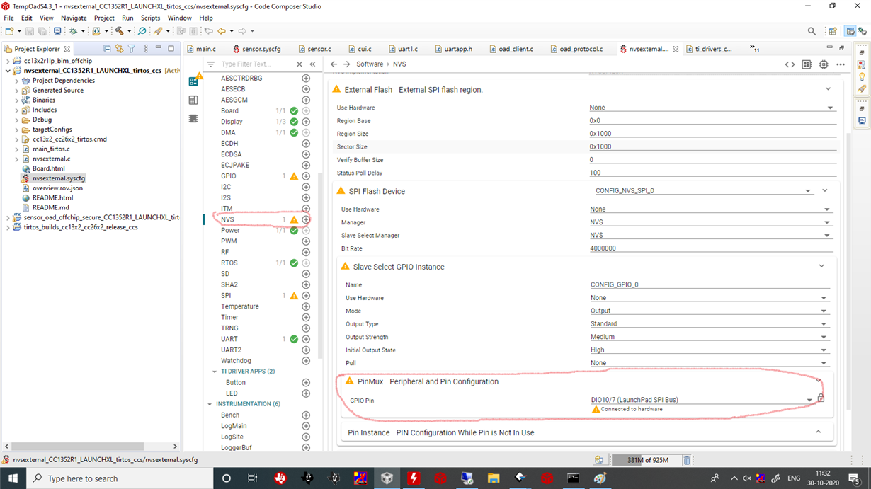
  • How have you set CS to DIO10? The only refrence I found was still tied to DIO20 which is used on the LP?

    I have attached screen shot of syscfg below. i highlighted in red color where i set CS pin.


    Have you monitored the SPI interface in the working and non working case to see what the delta is?

    sorry, im not getting this query

    Have you set "Use Custom Board"? If not, syscfg will use the pins that are mapped to the falsh on the selected launchpad. Look under "TI Drivers" -> GPIO for where the CS for the flash is defined. 

    Yes, i have set "Use custom Board".

  • Would you be able to send me the .syscfg file? Then I can import this in a project and see the resulting files. Note that in the original NVS project, the CS pin is set directly under GPIO driver, not under NVS.