

Other Parts Discussed in Thread: CC1310
Tool/software: Code Composer Studio
Hi Team,
SDK:simplelink_cc13x0_sdk_4_10_01_01
Example:gpiointerrupt
My customer now needs to configure GPIOCC26XX_DIO_21 as an interrupt triggered by a rising edge to connect to an external sensor.
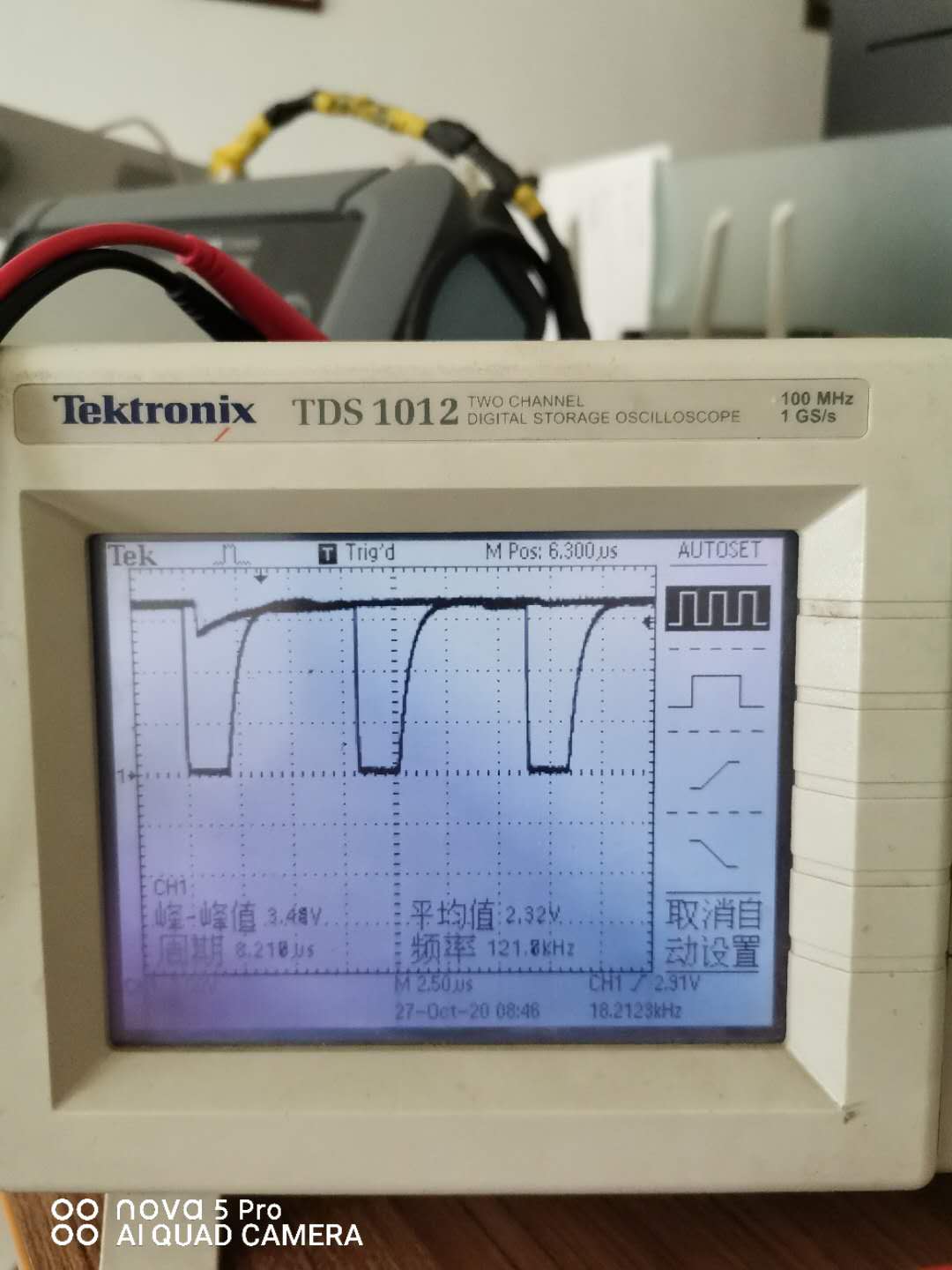
The sensor pin is output with a square wave signal cycle of 8us. The interrupt configuration is OK, and debugging can be interrupted.
Since the sensor has a conversion time of 20ms, that imeans every 20ms the sensor will output pulses with an 8us square wave signal.
The normal output should be about 1200. It is 1200 in stm32. But the number of pulses is only about 290 in CC1310 throgh DIO21.
Is it related to IO input rate?Could you help to check it?
int main(void)
{
/* Call driver init functions */
Board_init();

/* Start NoRTOS */
NoRTOS_start();

/* Call mainThread function */
mainThread(NULL);

while (1) {}
}

GPIO_setConfig(Board_GPIO_NST1001_P, GPIO_CFG_OUT_STD | GPIO_CFG_OUT_HIGH);
GPIO_setConfig(Board_GPIO_NST1001_DQ, GPIO_CFG_IN_NOPULL | GPIO_CFG_IN_INT_RISING);//DQ rising interrupt
GPIO_write(Board_GPIO_NST1001_P, 1);
/* install Button callback */
GPIO_setCallback(Board_GPIO_NST1001_DQ, NST1001_Int);

C_FLAG = 0; //
CPUdelay(1000); //
//usleep(1000);
/* Enable interrupts */
GPIO_enableInt(Board_GPIO_NST1001_DQ);

if(C_FLAG==1)
{
C_FLAG = 0;
//usleep(10000); //
CPUdelay(10000*48/4);// about 10000us
//Task_sleep(1000);

if(C_FLAG==0) //
{
GPIO_disableInt(Board_GPIO_NST1001_DQ); //

data_wendu[i] = (COUNT*0.0625f - 50.0625f); //
//printf("short = %2.1f---%d\n",data_wendu[i],COUNT);
data_wendu[i] = compensate_temp(data_wendu[i]);
sum_wd += data_wendu[i];
i++;

if(i>=10)
{
for(i=1,min=max=data_wendu[0];i<10;i++)
{
if(data_wendu[i]<min) min = data_wendu[i]; //
if(data_wendu[i]>max) max = data_wendu[i]; //
}
data_wendu_rul = (sum_wd-min-max)/(10-2); //
// printf("short = %2.1f---%d\n",data_wendu_rul,COUNT);
i = 0;
sum_wd = 0;
}

COUNT=0;
GPIO_enableInt(Board_GPIO_NST1001_DQ); //enable interrupt

GPIO_toggle(Board_GPIO_LED0);
}
}
The following is an 8us pulse signal output at a sensing interval of about 40ms:
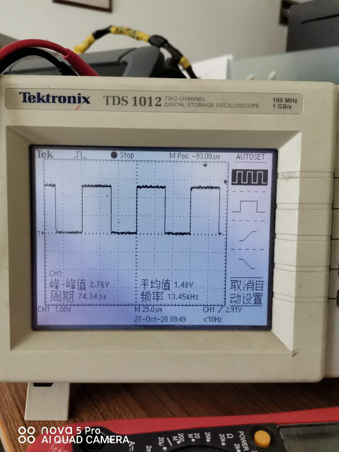
Put the LED flip indicator in the interrupt callback of IO21:
Regards,
Kevin
