This thread has been locked.

If you have a related question, please click the "Ask a related question" button in the top right corner. The newly created question will be automatically linked to this question.

CCS/LPSTK-CC1352R: I2C setup help in Sensor Controller Studio

Part Number: LPSTK-CC1352R

Tool/software: Code Composer Studio

Hello,

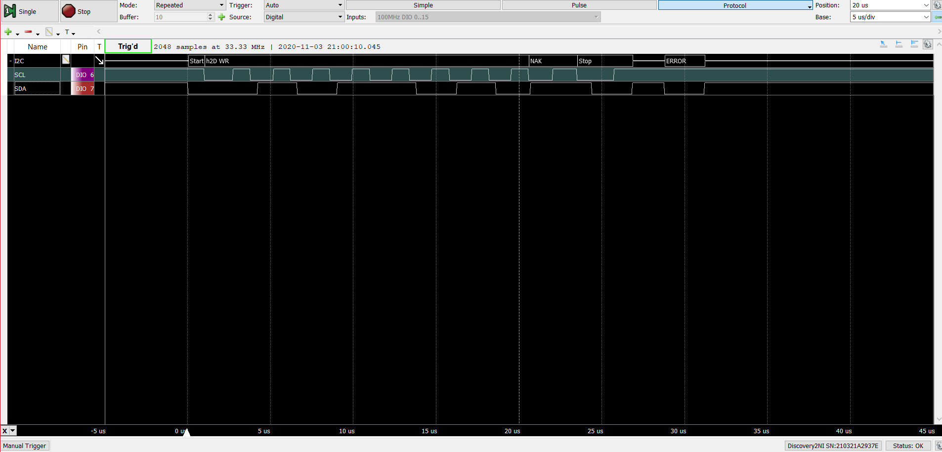
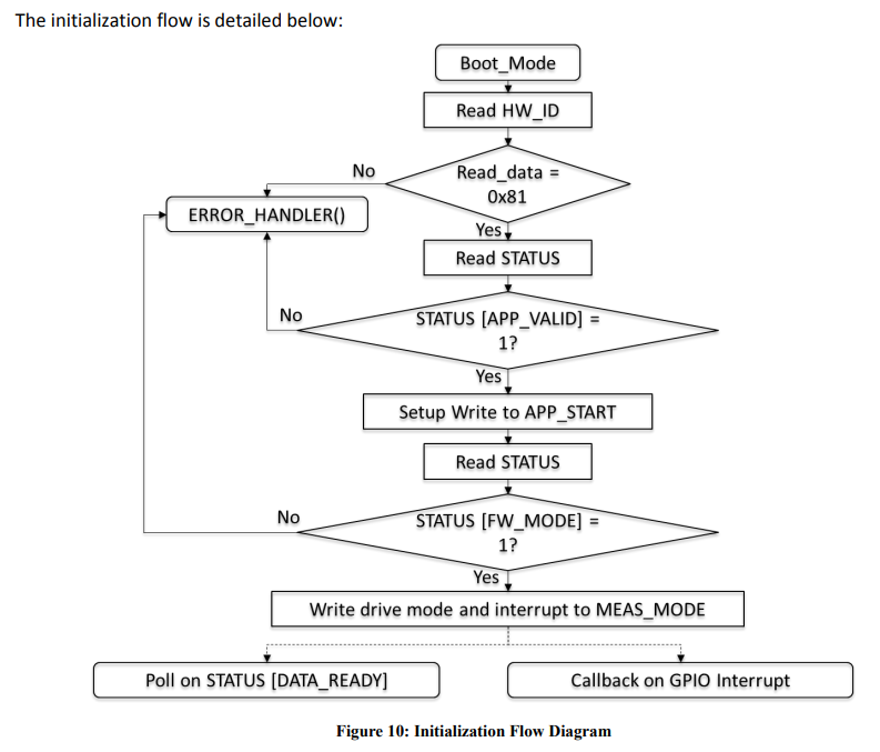
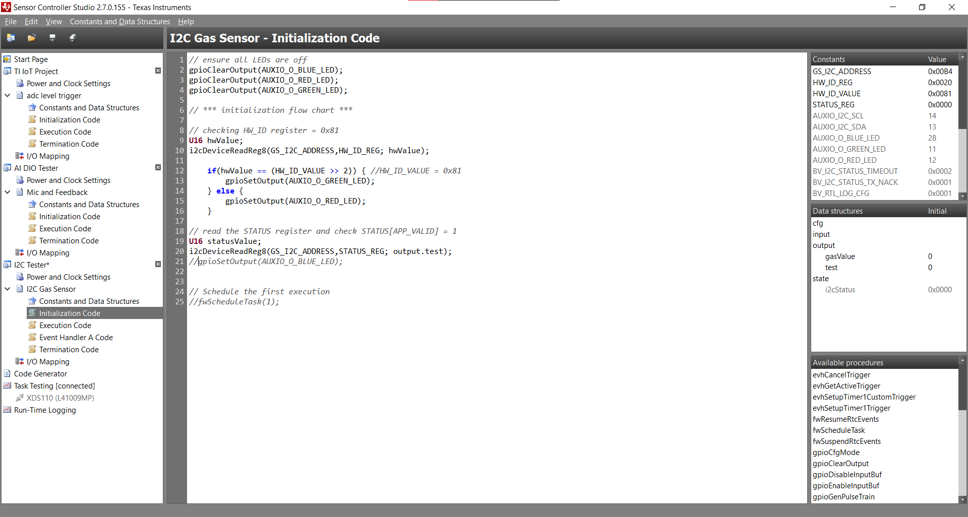
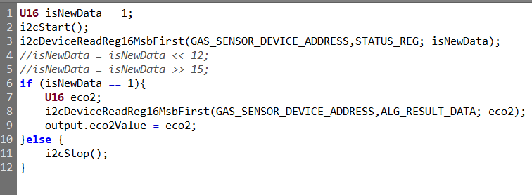
We are trying to use the I2C interface with the CCS811 gas sensor using Sensor Controller Studio (SCS). We are trying to follow along with the "I2C Light Sensor for LPSTK" example given in SCS. We started by trying to follow along with the initialization flow chart provided in the datasheet for the gas sensor. We cut out a few steps that we did not find necessary. We also are trying to use the "Timer 1 Event Trigger", as shown in the "I2C Light Sensor for LPSTK" example. In the Event A Handler Code, we tried to check the status register to determine if new data is available. After an "if" condition, we then tried to read data from the results register. Where we stand now, we do not seem to get any response from the gas sensor. Below shows two instances of code where we have found changes in the output:

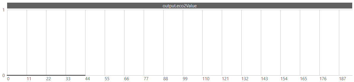
In this case, line 3 is not commented, and we read 0 when the code is ran.

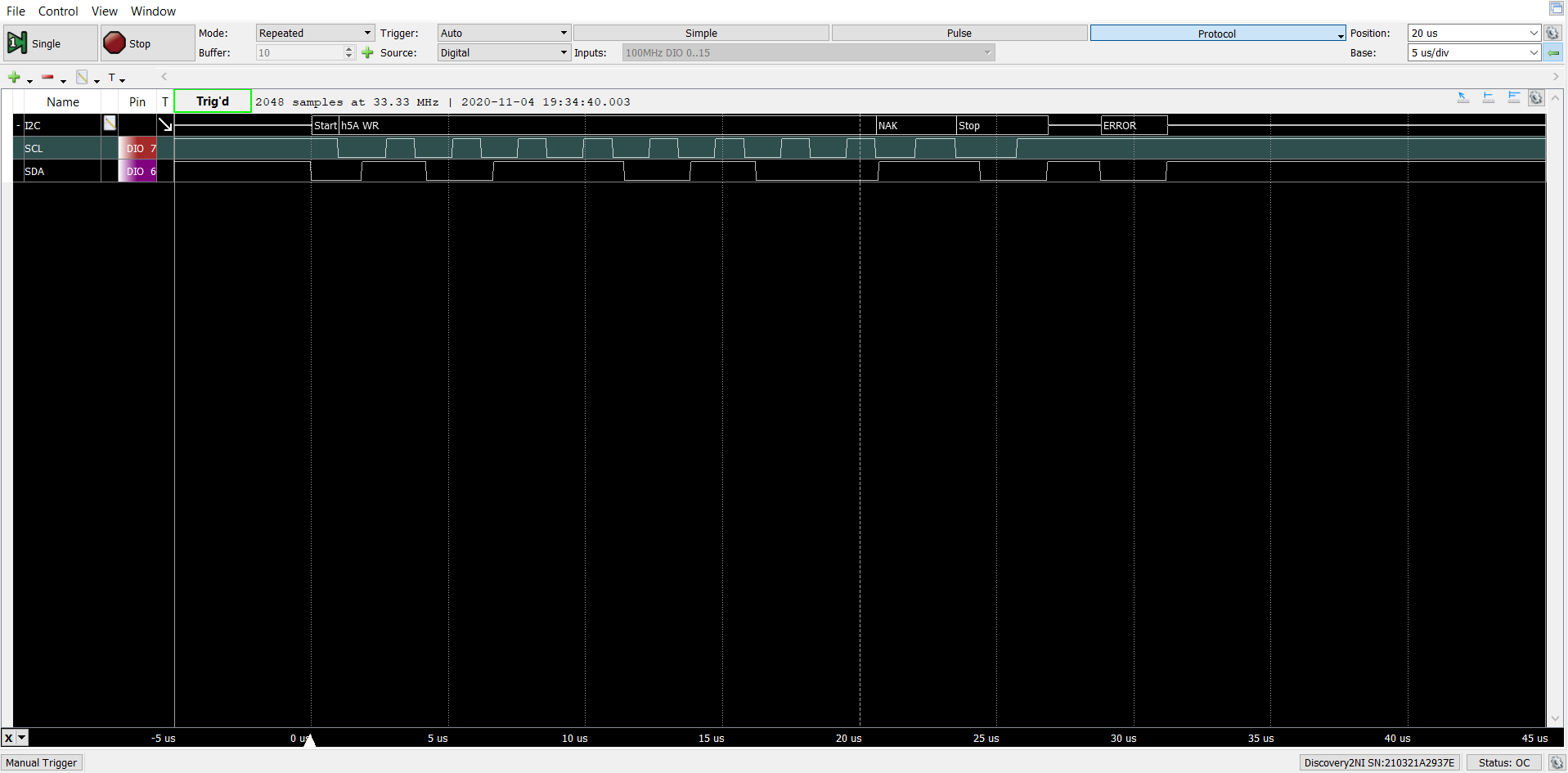
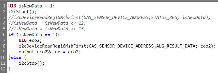
In this case, line 3 is commented, and we read 2 for the output:

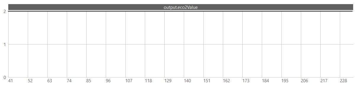
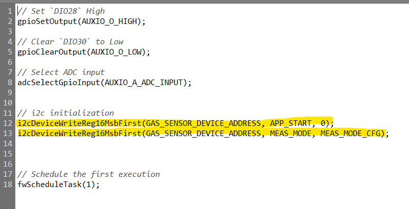
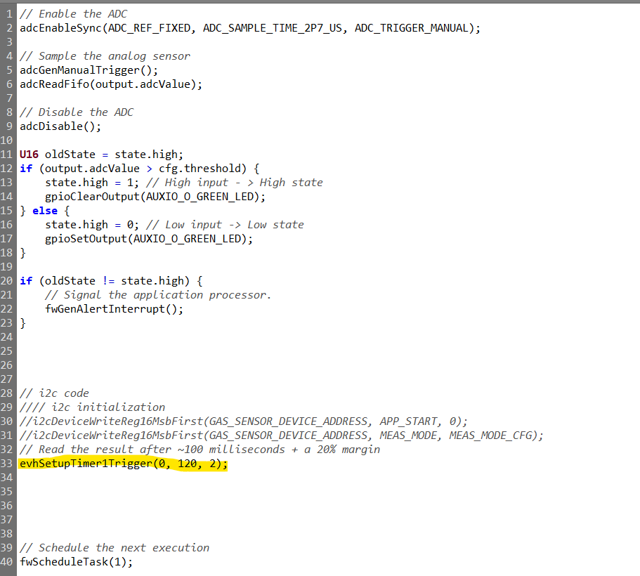
The existence of line 3 changes the I2C output, and we are wondering why this is. Also, see below for the initialization and execution code. Note that we are trying to add onto an existing ADC project that we have already verified that it works.

Thanks for your help.

  • Hi Alex,

    Can you double check the configuration of the gas sensor? Double check the lines used, start signal etc.

    It could also be relevant to attach a logic analyzer on the I2C pins.

  • What is the value of GAS_SENSOR_DEVICE_ADDRESS?

  • We managed to narrow down our issue and found that state.i2cStatus = 0x0001. This means the BV_I2C_STATUS_TX_NACK error is happening. How do we find out which byte needs to be acknowledged and acknowledge it to solve this problem?

    Thanks.

  • For the CCS811, the gas sensor 7-bit address is either 0x5A (low) or 0x5B (high) depending on the I2C_ADDR pin. I think it is naturally low, so it should be 0x5A. 

  • Here is a photo of the logic analyzer as we run the code that we have:

    It is detecting an error, but I am not sure how to interpret it or go about fixing it. Please let me know what you think.

  • Hi Alex,

    Looks like the address bytes are right-shifted when you send the packet (0x2D). Remember to left shift them. The 7-bit I2C slave address must be shifted left by 1 bit, both for high-level and low-level procedures.

  • Hi Marie,

    I tried your suggestion and shifted the 7-bit I2C slave address (0x5A) for the gas sensor to the left once and changed the 7-bit I2C slave address to 0xB4. Running the code this time around gave me a similar result as before:

    When developing the code for the gas sensor, we based it on the initialization chart from the datasheet (see below), but we cut out some parts that we thought were not necessary for our purposes. Do you think we need to try and implement each and every part of this chart? If so, how would we create an error handler?

    Thanks for all the help,

    Alex

  • I tried to take a step back, and I started with the top of the initialization chart. I found that I am not reading 0x81 from the HW_ID register. However, I am reading 0x81 >> 2, which comes out to be 32. Why is the value I am reading from the HW_ID register shifted right two bits?

    Beyond this, I tried to read from the STATUS register, and I could not read anything at all from there. The code below is what I am using in SCS. Please help I have no idea what I am doing wrong.

    Thanks,

    Alex

  • Hi Alex,

    I am not an expert on this gas meter, but it sounds like it could be worth while to follow the full process.