


Other Parts Discussed in Thread: OPT3001, ,
Hi,
My customer is testing communication with OPT3001 using I2C of Main CPU in the CC1310, but is experiencing waiting time by I2C continuous access.
On the other hand, when I2C communication is performed on the Sensor Controller side, this waiting time is not generated.
Why does this wait time occur when I2C communication is performed on the Main CPU?
Also, is there a way to eliminate this waiting time?
The following sample code is used for the Main CPU side." Only "i2ctmp.c" has been modified.

/*
 * Copyright (c) 2018-2019, Texas Instruments Incorporated
 * All rights reserved.
 *
 * Redistribution and use in source and binary forms, with or without
 * modification, are permitted provided that the following conditions
 * are met:
 *
 * *  Redistributions of source code must retain the above copyright
 *    notice, this list of conditions and the following disclaimer.
 *
 * *  Redistributions in binary form must reproduce the above copyright
 *    notice, this list of conditions and the following disclaimer in the
 *    documentation and/or other materials provided with the distribution.
 *
 * *  Neither the name of Texas Instruments Incorporated nor the names of
 *    its contributors may be used to endorse or promote products derived
 *    from this software without specific prior written permission.
 *
 * THIS SOFTWARE IS PROVIDED BY THE COPYRIGHT HOLDERS AND CONTRIBUTORS "AS IS"
 * AND ANY EXPRESS OR IMPLIED WARRANTIES, INCLUDING, BUT NOT LIMITED TO,
 * THE IMPLIED WARRANTIES OF MERCHANTABILITY AND FITNESS FOR A PARTICULAR
 * PURPOSE ARE DISCLAIMED. IN NO EVENT SHALL THE COPYRIGHT OWNER OR
 * CONTRIBUTORS BE LIABLE FOR ANY DIRECT, INDIRECT, INCIDENTAL, SPECIAL,
 * EXEMPLARY, OR CONSEQUENTIAL DAMAGES (INCLUDING, BUT NOT LIMITED TO,
 * PROCUREMENT OF SUBSTITUTE GOODS OR SERVICES; LOSS OF USE, DATA, OR PROFITS;
 * OR BUSINESS INTERRUPTION) HOWEVER CAUSED AND ON ANY THEORY OF LIABILITY,
 * WHETHER IN CONTRACT, STRICT LIABILITY, OR TORT (INCLUDING NEGLIGENCE OR
 * OTHERWISE) ARISING IN ANY WAY OUT OF THE USE OF THIS SOFTWARE,
 * EVEN IF ADVISED OF THE POSSIBILITY OF SUCH DAMAGE.
 */

/*
 *  ======== i2ctmp116.c ========
 */
#include <stdint.h>
#include <stddef.h>
#include <unistd.h>

/* Driver Header files */
#include <ti/drivers/GPIO.h>
#include <ti/drivers/I2C.h>
#include <ti/display/Display.h>

/* Example/Board Header files */
#include "Board.h"

#define TASKSTACKSIZE       640

/*
 *  ======== TMP Registers ========
 */
#define TMP006_REG          0x0001  /* Die Temp Result Register for TMP006 */
#define TMP116_REG          0x0000  /* Die Temp Result Register for TMP116 */

#define OPT3001_ADDR        0x44;
#define TMP116_BP_ADDR      0x48;
#define TMP116_LP_ADDR      0x49;

static Display_Handle display;

/*
 *  ======== mainThread ========
 */
void *mainThread(void *arg0)
{
    uint16_t        sample;
    uint16_t        temperature;
    uint8_t         txBuffer[8];
    uint8_t         rxBuffer[8];
    I2C_Handle i2c;
    I2C_Params i2cParams;
    I2C_Transaction i2cTransaction;

    /* Call driver init functions */
    Display_init();
    GPIO_init();
    I2C_init();

    /* Configure the LED and if applicable, the TMP116_EN pin */
    GPIO_setConfig(Board_GPIO_LED0, GPIO_CFG_OUT_STD | GPIO_CFG_OUT_LOW);
#ifdef Board_GPIO_TMP116_EN
    GPIO_setConfig(Board_GPIO_TMP116_EN, GPIO_CFG_OUT_STD | GPIO_CFG_OUT_HIGH);
    /* 1.5 ms reset time for the TMP116 */
    sleep(1);
#endif

    /* Open the HOST display for output */
    display = Display_open(Display_Type_UART, NULL);
    if (display == NULL) {
        while (1);
    }

    /* Turn on user LED */
    GPIO_write(Board_GPIO_LED0, Board_GPIO_LED_ON);
    Display_printf(display, 0, 0, "Starting the i2ctmp example.");

    /* Create I2C for usage */
    I2C_Params_init(&i2cParams);
    i2cParams.bitRate = I2C_400kHz;
    i2c = I2C_open(Board_I2C_TMP, &i2cParams);
    if (i2c == NULL) {
        Display_printf(display, 0, 0, "Error Initializing I2C\n");
        while (1);
    }
    else {
        Display_printf(display, 0, 0, "I2C Initialized!\n");
    }

    /* Common I2C transaction setup */
    i2cTransaction.writeBuf   = txBuffer;
    i2cTransaction.writeCount = 0;
    i2cTransaction.readBuf    = rxBuffer;
    i2cTransaction.readCount  = 0;
    i2cTransaction.slaveAddress = OPT3001_ADDR;

    /* Take 20 samples and print them out onto the console */
    for (;;) {
        txBuffer[0] = 0x01;
        txBuffer[1] = 0xC2;
        txBuffer[2] = 0x10;
        i2cTransaction.writeCount = 3;
        i2cTransaction.readCount  = 0;
        i2cTransaction.slaveAddress = OPT3001_ADDR;
        if (!I2C_transfer(i2c, &i2cTransaction)) {
            Display_printf(display, 0, 0, "Error. No TMP sensor found!");
        }

        usleep(150000);

        txBuffer[0] = 0x00;
        i2cTransaction.writeCount = 1;
        i2cTransaction.readCount  = 2;
        if (I2C_transfer(i2c, &i2cTransaction)) {
            uint8_t exp = rxBuffer[0] >> 4;
            uint16_t fraction = ((rxBuffer[0] & 0x0f) << 8) | rxBuffer[1];
            uint32_t lux = (uint32_t)(2 << (exp - 1)) * (uint32_t)fraction;
            Display_printf(display, 0, 0, "Sample %u", lux);
        }
        else {
            Display_printf(display, 0, 0, "I2C Bus fault.");
        }

        /* Sleep for 1 second */
        usleep(200000);
    }

    I2C_close(i2c);
    Display_printf(display, 0, 0, "I2C closed!");

    return (NULL);
}
The Sensor Controller side is created based on the "I2C Light Sensor" sample software included in Sensor Controller Studio.
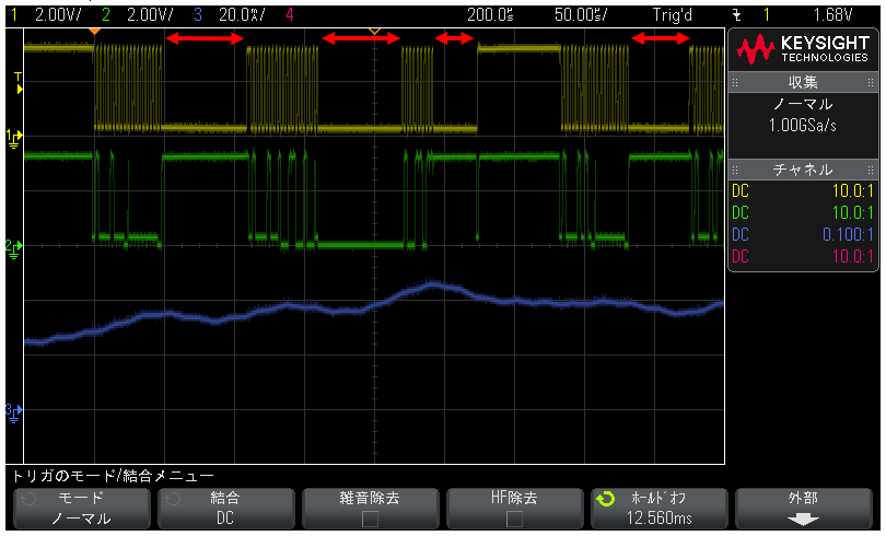
The following is a waveform image of the Main CPU side during I2C communication.
The board used is LAUNCHXL-CC1310.
Ch.1 (yellow): SCL (2V/div)
Ch.2(Green): SDA(2V/div)
Ch.3 (blue) : Current consumption waveform (2mA/div)
The red arrows indicate the waiting time that is occurring.
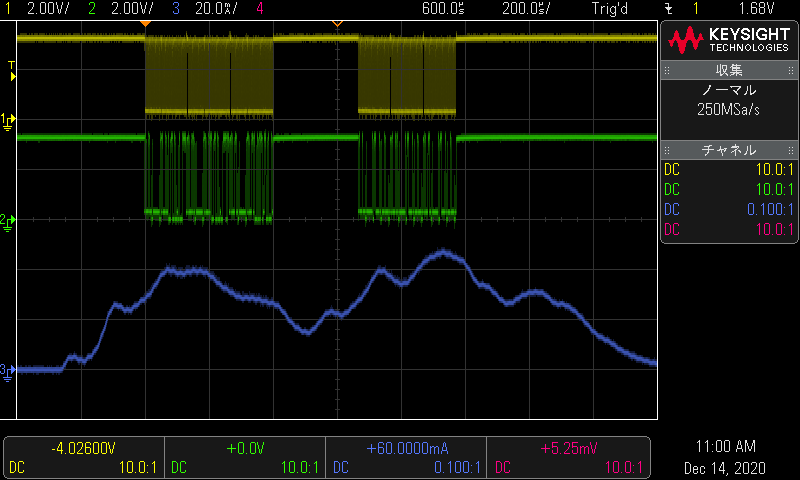
The following is the waveform of the Sensor Controller side during I2C communication.
The board used is LAUNCHXL-CC1310.
Ch.1 (yellow): SCL (2V/div)
Ch.2(Green): SDA(2V/div)
Ch.3 (blue) : Current consumption waveform (2mA/div)
Best Regards,
UNA

