This thread has been locked.

If you have a related question, please click the "Ask a related question" button in the top right corner. The newly created question will be automatically linked to this question.

CC1352P: Clarification on IPC balun document for 20dBm output

Part Number: CC1352P

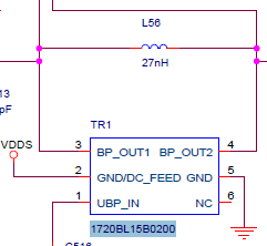
In the attached TI document, a balun IPC is detailed for both sub-1 and 2.4 GHz use, however, the CC1352P also has a designated 20dBm TX output for sub-1GHZ, which in the demo board (LAUNCHXL-CC1352P1) has a totally different balun arrangement. Can the suggested Murata/JTI baluns also be used for the high power output i.e. will I need to place two baluns? Nowhere in the document is this specified. Also, if I use the IPC balun for the high power output, do I need to connect the RX_TX line? In the LAUNCHXL-CC1352P1 schematic, the high-power output network is not electrically connected to RX_TX, as shown in the photo.6305.swra629a.pdf

  • Hi,

    The IPC matched-balun for the standard sub-1 GHz and 2.4 GHz port cannot be used for the PA port since they have totally different impedances.

    Regards,

       Richard

  • That's a bummer. Do you know what the impedance of that PA port is so I can try to match it? Or where I might find such information? The datasheet does not mention.

    Thanks,

    Xavier

  • Hi,

    The load impedances are specified in the app note "CC13xx/CC26xx Hardware Configuration and PCB Design Considerations".


    The PA port wants to see a load of approx 200 ohm.

    One option could be to use a Marchand balun 200:50 (part number: 1720BL15B0200 from Johanson Technology). Use an extra inductance (L56) between the balanced ports for impedance optimizing.

    Then you would need to filter the harmonics on the unbalanced port. 

    Still recommend to follow the standard ref design. Using a wideband balun plus filtering will not have a significantly lower component count and could be more expensive.

    Regards,

       Richard

  • Thanks Richard, I appreciate it.