Hi,
I have a custom board with CC1310, My project is using XDCtools [3.51.3.28_core] and SimpleLink CC13x0 SDK[4.10.1.01]. Today I want to make some spi communication with bma400 mems. I searched Sub-1 GHz forum and looked at the spimaster project and did something. But I am not sure if my communication is ok. If it is ok, why I can't see my slave's id ? Could you please suggest me to do something ?
1 ) First of all, I am consufed with pin init, there are lots of example. What is the true init ?
PIN_Config SPIPinTable[] =
{
//1
     MEMS_MOSI | PIN_GPIO_OUTPUT_EN | PIN_NOPULL   | PIN_PUSHPULL | PIN_DRVSTR_MAX,
     MEMS_MISO | PIN_INPUT_EN       | PIN_NOPULL   | PIN_DRVSTR_MAX,
     MEMS_CLK  | PIN_GPIO_OUTPUT_EN | PIN_GPIO_LOW | PIN_PUSHPULL | PIN_DRVSTR_MAX,
     MEMS_CSN  | PIN_GPIO_OUTPUT_EN | PIN_GPIO_LOW | PIN_PUSHPULL | PIN_DRVSTR_MAX,

//2
//     MEMS_MOSI | PIN_INPUT_EN | PIN_PULLDOWN,
//     MEMS_MISO | PIN_INPUT_EN | PIN_PULLDOWN,
//     MEMS_CLK  | PIN_INPUT_EN | PIN_PULLDOWN,
//     MEMS_CSN  | PIN_GPIO_OUTPUT_EN | PIN_GPIO_LOW | PIN_PUSHPULL | PIN_DRVSTR_MAX,

//3
//     MEMS_MOSI | PIN_INPUT_EN | PIN_PULLDOWN,
//     MEMS_MISO | PIN_GPIO_OUTPUT_EN | PIN_GPIO_HIGH | PIN_PUSHPULL,
//     MEMS_CLK | PIN_INPUT_EN | PIN_PULLDOWN,
//     MEMS_CSN | PIN_BM_INPUT_EN | PIN_PULLDOWN,

//4
// MEMS_MOSI| PIN_GPIO_OUTPUT_EN | PIN_GPIO_HIGH | PIN_PUSHPULL,
// MEMS_MISO| PIN_INPUT_EN | PIN_PULLDOWN,
// MEMS_CLK | PIN_INPUT_EN | PIN_PULLDOWN,
// MEMS_CSN | PIN_GPIO_OUTPUT_EN | PIN_GPIO_HIGH | PIN_PUSHPULL | PIN_DRVSTR_MIN,

     MEMS_INT1 | PIN_GPIO_OUTPUT_EN | PIN_GPIO_LOW | PIN_PUSHPULL | PIN_DRVSTR_MAX,
     MEMS_INT2 | PIN_GPIO_OUTPUT_EN | PIN_GPIO_LOW | PIN_PUSHPULL | PIN_DRVSTR_MAX,
     PIN_TERMINATE
};
2 ) I have changed CC1310_LAUNCHXL.c and CC1310_LAUNCHXL.h files as below. If it is not okay, please tell me. I especially want you to look at the SPI part and is it okay to delete another parts I won't use ?
#ifndef CC1310_H_
#define CC1310_H_

#ifdef __cplusplus
extern "C" {
#endif

#include <ti/drivers/PIN.h>
#include <ti/devices/cc13x0/driverlib/ioc.h>

#define STA_LED               IOID_16
#define MEMS_INT2             IOID_15
#define MEMS_INT1             IOID_14
#define MEMS_MOSI             IOID_13
#define MEMS_MISO             IOID_12
#define MEMS_CLK              IOID_11
#define MEMS_CSN              IOID_10

#define TEMP_SCL0             IOID_9
#define TEMP_SDA0             IOID_8

typedef enum CC1310_LAUNCHXL_I2CName {
    CC1310_LAUNCHXL_I2C0 = 0,

    CC1310_LAUNCHXL_I2CCOUNT
} CC1310_LAUNCHXL_I2CName;

typedef enum CC1310_LAUNCHXL_SPIName {
    CC1310_LAUNCHXL_SPI0 = 0,
    CC1310_LAUNCHXL_SPI1,

    CC1310_LAUNCHXL_SPICOUNT
} CC1310_LAUNCHXL_SPIName;

typedef enum CC1310_LAUNCHXL_UDMAName {
    CC1310_LAUNCHXL_UDMA0 = 0,

    CC1310_LAUNCHXL_UDMACOUNT
} CC1310_LAUNCHXL_UDMAName;

typedef enum CC1310_LAUNCHXL_WatchdogName {
    CC1310_LAUNCHXL_WATCHDOG0 = 0,

    CC1310_LAUNCHXL_WATCHDOGCOUNT
} CC1310_LAUNCHXL_WatchdogName;


#ifdef __cplusplus
}
#endif

#endif
#include <CC1310.h>
#include <stdbool.h>
#include <stddef.h>
#include <stdint.h>
#include <ti/devices/cc13x0/driverlib/ioc.h>
#include <ti/devices/cc13x0/driverlib/udma.h>
#include <ti/devices/cc13x0/inc/hw_ints.h>
#include <ti/devices/cc13x0/inc/hw_memmap.h>
#include <ti/drivers/adcbuf/ADCBufCC26XX.h>

/*
 *  =============================== I2C ===============================
*/
#include <ti/drivers/I2C.h>
#include <ti/drivers/i2c/I2CCC26XX.h>

I2CCC26XX_Object i2cCC26xxObjects[CC1310_LAUNCHXL_I2CCOUNT];

const I2CCC26XX_HWAttrsV1 i2cCC26xxHWAttrs[CC1310_LAUNCHXL_I2CCOUNT] = {
    {
        .baseAddr    = I2C0_BASE,
        .powerMngrId = PowerCC26XX_PERIPH_I2C0,
        .intNum      = INT_I2C_IRQ,
        .intPriority = ~0,
        .swiPriority = 0,
        .sdaPin      = TEMP_SDA0,
        .sclPin      = TEMP_SCL0,
    }
};

const I2C_Config I2C_config[CC1310_LAUNCHXL_I2CCOUNT] = {
    {
        .fxnTablePtr = &I2CCC26XX_fxnTable,
        .object      = &i2cCC26xxObjects[CC1310_LAUNCHXL_I2C0],
        .hwAttrs     = &i2cCC26xxHWAttrs[CC1310_LAUNCHXL_I2C0]
    }
};

const uint_least8_t I2C_count = CC1310_LAUNCHXL_I2CCOUNT;

/*
 *  =============================== PIN ===============================
 */
#include <ti/drivers/PIN.h>
#include <ti/drivers/pin/PINCC26XX.h>

const PINCC26XX_HWAttrs PINCC26XX_hwAttrs = {
    .intPriority = ~0,
    .swiPriority = 0
};

/*
 *  =============================== Power ===============================
 */
#include <ti/drivers/Power.h>
#include <ti/drivers/power/PowerCC26XX.h>

const PowerCC26XX_Config PowerCC26XX_config = {
    .policyInitFxn      = NULL,
    .policyFxn          = &PowerCC26XX_standbyPolicy,
    .calibrateFxn       = &PowerCC26XX_calibrate,
    .enablePolicy       = true,
    .calibrateRCOSC_LF  = true,
    .calibrateRCOSC_HF  = true,
};

/*
 *  =============================== RF Driver ===============================
 */
#include <ti/drivers/rf/RF.h>

const RFCC26XX_HWAttrsV2 RFCC26XX_hwAttrs = {
    .hwiPriority        = ~0,       /* Lowest HWI priority */
    .swiPriority        = 0,        /* Lowest SWI priority */
    .xoscHfAlwaysNeeded = true,     /* Keep XOSC dependency while in standby */
    .globalCallback     = NULL,     /* No board specific callback */
    .globalEventMask    = 0         /* No events subscribed to */
};

/*
 *  =============================== SPI DMA ===============================
 */
#include <ti/drivers/SPI.h>
#include <ti/drivers/spi/SPICC26XXDMA.h>

SPICC26XXDMA_Object spiCC26XXDMAObjects[CC1310_LAUNCHXL_SPICOUNT];

/*
 * NOTE: The SPI instances below can be used by the SD driver to communicate
 * with a SD card via SPI.  The 'defaultTxBufValue' fields below are set to 0xFF
 * to satisfy the SDSPI driver requirement.
 */
const SPICC26XXDMA_HWAttrsV1 spiCC26XXDMAHWAttrs[CC1310_LAUNCHXL_SPICOUNT] = {
    {
        .baseAddr           = SSI0_BASE,
        .intNum             = INT_SSI0_COMB,
        .intPriority        = ~0,
        .swiPriority        = 0,
        .powerMngrId        = PowerCC26XX_PERIPH_SSI0,
        .defaultTxBufValue  = 0,
        .rxChannelBitMask   = 1<<UDMA_CHAN_SSI0_RX,
        .txChannelBitMask   = 1<<UDMA_CHAN_SSI0_TX,
        .mosiPin            = MEMS_MOSI,
        .misoPin            = MEMS_MISO,
        .clkPin             = MEMS_CLK,
        .csnPin             = MEMS_CSN,
//        .minDmaTransferSize = 10
    },
    {
        .baseAddr           = SSI1_BASE,
        .intNum             = INT_SSI1_COMB,
        .intPriority        = ~0,
        .swiPriority        = 0,
        .powerMngrId        = PowerCC26XX_PERIPH_SSI1,
        .defaultTxBufValue  = 0,
        .rxChannelBitMask   = 1<<UDMA_CHAN_SSI1_RX,
        .txChannelBitMask   = 1<<UDMA_CHAN_SSI1_TX,
        .mosiPin            = 0xFF,
        .misoPin            = 0xFF,
        .clkPin             = 0xFF,
        .csnPin             = 0xFF,
//        .minDmaTransferSize = 10
    }
};

const SPI_Config SPI_config[CC1310_LAUNCHXL_SPICOUNT] = {
    {
         .fxnTablePtr = &SPICC26XXDMA_fxnTable,
         .object      = &spiCC26XXDMAObjects[CC1310_LAUNCHXL_SPI0],
         .hwAttrs     = &spiCC26XXDMAHWAttrs[CC1310_LAUNCHXL_SPI0]
    },
    {
         .fxnTablePtr = &SPICC26XXDMA_fxnTable,
         .object      = &spiCC26XXDMAObjects[CC1310_LAUNCHXL_SPI1],
         .hwAttrs     = &spiCC26XXDMAHWAttrs[CC1310_LAUNCHXL_SPI1]
    },
};

const uint_least8_t SPI_count = CC1310_LAUNCHXL_SPICOUNT;

/*
 *  =============================== UDMA ===============================
 */
#include <ti/drivers/dma/UDMACC26XX.h>

UDMACC26XX_Object udmaObjects[CC1310_LAUNCHXL_UDMACOUNT];

const UDMACC26XX_HWAttrs udmaHWAttrs[CC1310_LAUNCHXL_UDMACOUNT] = {
    {
        .baseAddr    = UDMA0_BASE,
        .powerMngrId = PowerCC26XX_PERIPH_UDMA,
        .intNum      = INT_DMA_ERR,
        .intPriority = ~0
    }
};

const UDMACC26XX_Config UDMACC26XX_config[CC1310_LAUNCHXL_UDMACOUNT] = {
    {
         .object  = &udmaObjects[CC1310_LAUNCHXL_UDMA0],
         .hwAttrs = &udmaHWAttrs[CC1310_LAUNCHXL_UDMA0]
    },
};

/*
 *  =============================== Watchdog ===============================
 */
#include <ti/drivers/Watchdog.h>
#include <ti/drivers/watchdog/WatchdogCC26XX.h>

WatchdogCC26XX_Object watchdogCC26XXObjects[CC1310_LAUNCHXL_WATCHDOGCOUNT];

const WatchdogCC26XX_HWAttrs watchdogCC26XXHWAttrs[CC1310_LAUNCHXL_WATCHDOGCOUNT] = {
    {
        .baseAddr    = WDT_BASE,
        .reloadValue = 1000 /* Reload value in milliseconds */
    },
};

const Watchdog_Config Watchdog_config[CC1310_LAUNCHXL_WATCHDOGCOUNT] = {
    {
        .fxnTablePtr = &WatchdogCC26XX_fxnTable,
        .object      = &watchdogCC26XXObjects[CC1310_LAUNCHXL_WATCHDOG0],
        .hwAttrs     = &watchdogCC26XXHWAttrs[CC1310_LAUNCHXL_WATCHDOG0]
    },
};

const uint_least8_t Watchdog_count = CC1310_LAUNCHXL_WATCHDOGCOUNT;
3 ) Let's see SPI function,
#define SPI_MSG_LENGTH (2)
unsigned char txBuf[SPI_MSG_LENGTH];
unsigned char rxBuf[SPI_MSG_LENGTH];
void AccelTaskFunction(UArg arg0, UArg arg1)
{
SPI_Handle masterSpi;
SPI_Params params;
SPI_Transaction transaction;
bool transferOK;
SPI_init();
SPI_Params_init(¶ms);
params.bitRate = 1000000;
params.dataSize = 8;
params.frameFormat = SPI_POL0_PHA0;
params.mode = SPI_MASTER;
params.transferCallbackFxn = NULL;
params.transferMode= SPI_MODE_BLOCKING;
// params.transferTimeout = SPI_WAIT_FOREVER;
masterSpi = SPI_open(0, ¶ms);
if (masterSpi == NULL) {
while (1);
}
while(1)
{
usleep(954400);//almost 1 second wait
txBuf[0] = 0x00;
txBuf[1] = 0x00;
transaction.count = 2;
transaction.txBuf = txBuf;
// transaction.rxBuf = NULL;
transaction.rxBuf = rxBuf;
transferOK = SPI_transfer(masterSpi, &transaction);
}
}
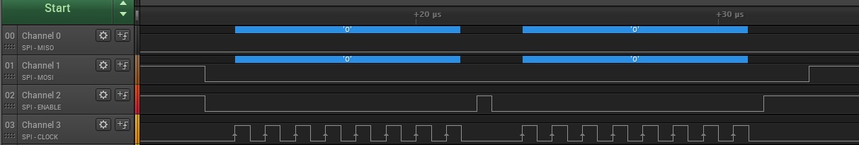
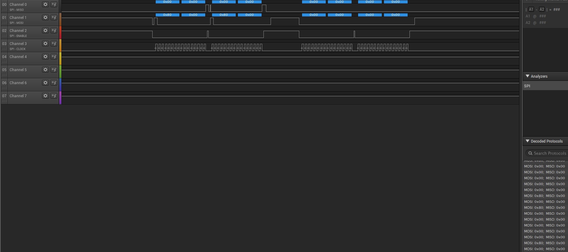
4 ) here is the logic analyzer output. I see a warning as below in first communication try.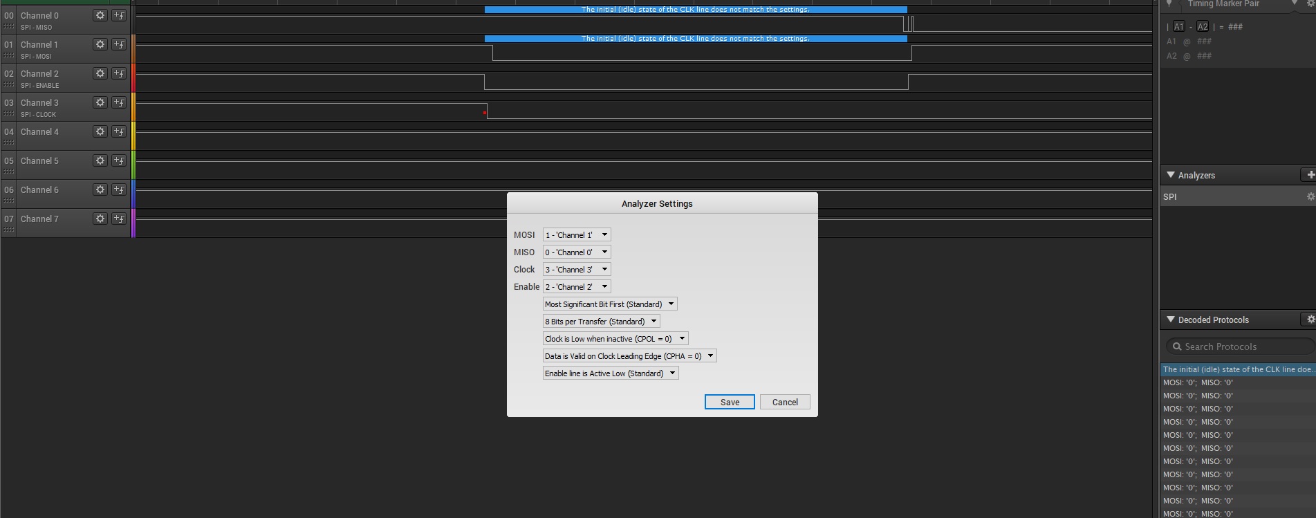
and I send 0x00 0x00 to bma400 to read it's chip id. The answer is as below.