This thread has been locked.

If you have a related question, please click the "Ask a related question" button in the top right corner. The newly created question will be automatically linked to this question.

CCS/CC1350: cc1350

Part Number: CC1350
Other Parts Discussed in Thread: CC1310

Tool/software: Code Composer Studio

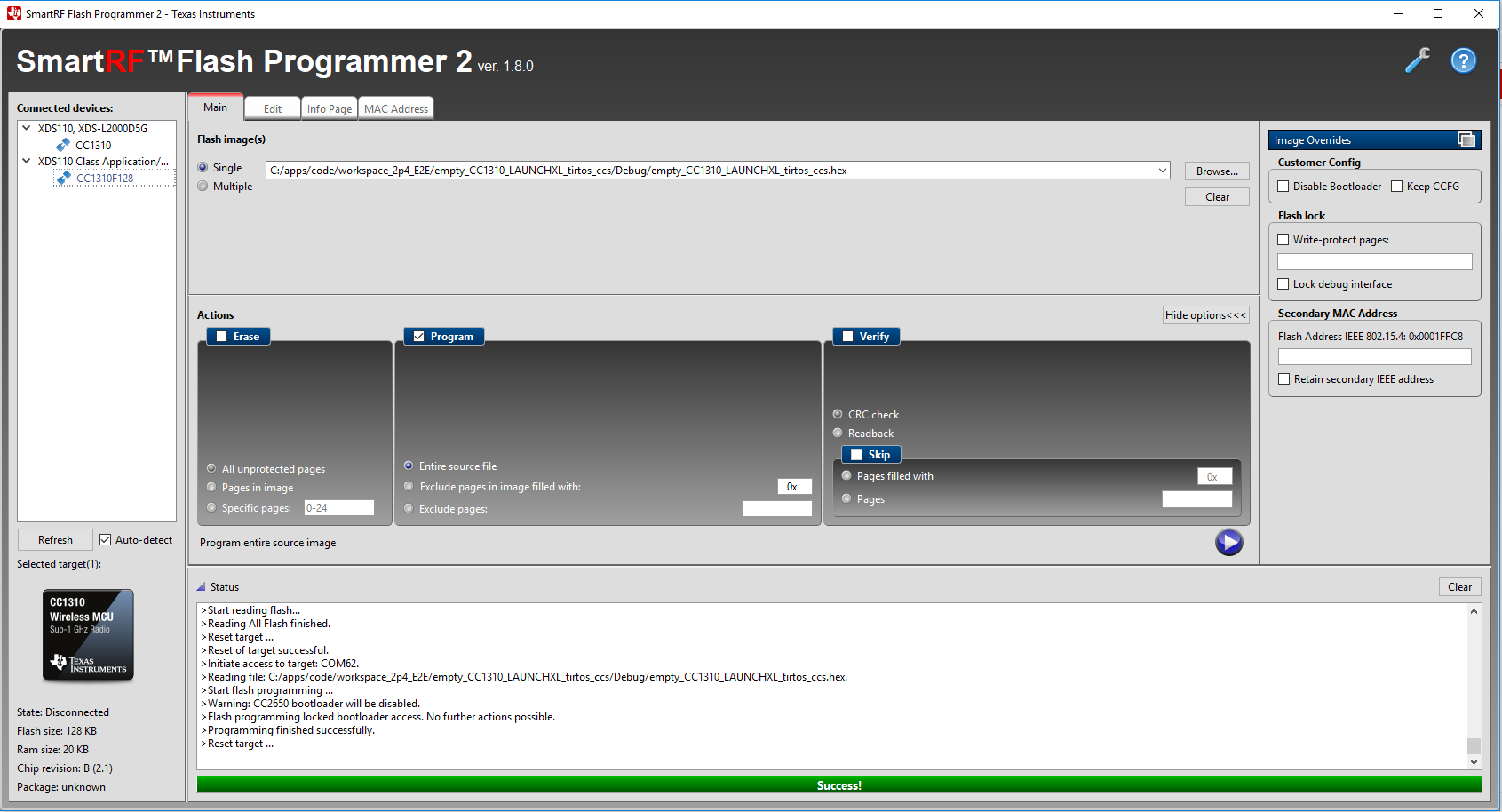
how can i flash code into cc1350 using uart and smart rf flash programmer

am new to ccs n smart rf i red ti boot loader  but not getting clear view any help with out using xds110 debuger

  • The first question: Have you read the flash programmer 2 help since it's covered in the help how to flash via UART.

    The second question is a double post of e2e.ti.com/.../768873
  • yes i red 

    am getting error like unable to enter into boot loader mode(when i click on connect com port )

    may i know how to check cc1350 entered into boot loader mode or not

  • If you get a green connect symbol you are in bootloader mode (see the Flash Programmer 2 help)

    You write that you have read the document I linked to but you do not write anything about what you have tried to comply with figure 1.
    - Have you tried mass erase to ensure that you have a empty flash?
    - Have you tried to define a pin as bootloader backdoor?
  • Closing this thread since you also have this e2e.ti.com/.../2844086 open. Please only post once.
  • if i try to mass erase it is showing that error

    if i try to play directly it is showing flashing program successful but in my code i have written blinking led it is not doing that 

    and my code is(config file chnages)

    //#####################################
    // Bootloader settings
    //#####################################

    #ifndef SET_CCFG_BL_CONFIG_BOOTLOADER_ENABLE
    //#define SET_CCFG_BL_CONFIG_BOOTLOADER_ENABLE 0x00 // Disable ROM boot loader
    #define SET_CCFG_BL_CONFIG_BOOTLOADER_ENABLE 0xC5 // Enable ROM boot loader
    #endif

    #ifndef SET_CCFG_BL_CONFIG_BL_LEVEL
    //#define SET_CCFG_BL_CONFIG_BL_LEVEL 0x0 // Active low to open boot loader backdoor
    #define SET_CCFG_BL_CONFIG_BL_LEVEL 0x1 // Active high to open boot loader backdoor
    #endif

    #ifndef SET_CCFG_BL_CONFIG_BL_PIN_NUMBER
    #define SET_CCFG_BL_CONFIG_BL_PIN_NUMBER 0x12 // DIO number for boot loader backdoor
    #endif

    #ifndef SET_CCFG_BL_CONFIG_BL_ENABLE
    #define SET_CCFG_BL_CONFIG_BL_ENABLE 0xC5 // Enabled boot loader backdoor
    //#define SET_CCFG_BL_CONFIG_BL_ENABLE 0xFF // Disabled boot loader backdoor
    #endif

  • - You can not do mass erase over UART, this has to be done over JTAG.
    - As I understand it you actually manage to flash the chip over UART but you don't get the expected functionality after you have reseted the board. If you read out the flash using the JTAG interface, is the content of the flash the same as the .hex file you flashed the chip with?
  • yes same .hex file i flashed
  • and one more issue is first it has shown like initiate access to com5 success now it is failing
  • Part Number: CC1350

    If problem persists, check connection and baud rate.

    >Connecting over serial bootloader failed: No response from device. Device may not be in bootloader mode. Reset device and try again.

    If problem persists, check connection and baud rate.

    >Failed to create device object.

    am getting that error when i try to connect usb port in smart rf flash programmer 

    any suggestion please

  • I assume that this is the same issue that is covered in: e2e.ti.com/.../768859 ?
  • but that did not resolved my issue

    i changed config file settings (enabling boot loader and bl_pin i set as 12)

    to cc1350 i connected usb to ttl terminal (tx-rx , rx-tx,vcc and gnd)
    and am checking in smart rf flash programmer

    do i need to make any chnges or what
  • Do you do mass erase to your CC1350 before you try to connect to it from Flash Programmer 2 with serial connection?
  • if i do mass erase using xds then it is connecting but am not getting expected output

    >Initiate access to target: XDS-L40004YT.
    >Start flash erase ...
    >Erase finished successfully.
    >Reset target ...
    >Reset of target successful.
    >Initiate access to target: COM5.
    >Reading file: C:/Users/workspace/empty_CC1350_LAUNCHXL_TI/Debug/empty_CC1350_LAUNCHXL_TI.hex.
    >Start flash erase ...
    >Erase finished successfully.
    >Start flash programming ...
    >Programming finished successfully.
    >Reset target ...
    >Reset of target successful.
  • The log shows everything works successfully.
  • - It's not possible for be to know why you suddenly get connection issues. If you use the bootloader backdoor the method to connect to the board should behave the same way always. Are you trying to connect to the target at the same way always?
    - Have you tried to flash using the .out file to see if the LED blink in this case? Could you confirm that you get the same response if you flash the chip using the jtag interface?
    - Which hex file format have you used?
  • but not getting expected output
    may i know if i did anything wrong
  • yes every time am connecting in the same way

    if i try to flash .out file also it is showing the same flashed successfully but no output(if i do with jtag it is blinking)

    i was tried to flash .hex file
  • Please stop double posting.
  • I think “#define SET_CCFG_BL_CONFIG_BL_PIN_NUMBER 0x12 ” means to use DIO_18 not DIO_12 as boot loader pin.
  • Hi, we are working on TI CC1350 launchpad. We are trying to evaluate how to flash code through UART using Smart RF Flash Programmer2. We are evaluating this because we are building our own board and we want to use this feature.

    We have followed the instructions available on the forum and technical reference manual.

    We are using the LED blinking example for this testing. (This example is working fine when we download using XDS debugger)
    When we flash the .hex file in Smart RF Flash Programmer2, it shows successfully flashed.

    When we flash we are able to see the below status on the flash programmer:
    >Start flash programming ...

    >Programming finished successfully.

    >Reset target ...

    >Reset of target successful.

    This means it has entered into boot loader mode and flashed successfully. Isn't it?


    But we are not able to see the led blink (no response from controller we believe). What can be the reason. We are sure about the .hex file because when flashed using XDS it works. But when we flash using UART it doesn't.

    One more thing we observed was:

    We need to mass erase the controller every time before we flash the .hex file, else it shows error.

    Is this needed and if yes, can we make any changes in code so that when we flash the .hex file, the older image will get erased automatically?

    Please find more details below:

    Following changes were made in config file:

    #ifndef SET_CCFG_BL_CONFIG_BOOTLOADER_ENABLE
    //#define SET_CCFG_BL_CONFIG_BOOTLOADER_ENABLE 0x00 // Disable ROM boot loader
    #define SET_CCFG_BL_CONFIG_BOOTLOADER_ENABLE 0xC5 // Enable ROM boot loader
    #endif

    #ifndef SET_CCFG_BL_CONFIG_BL_LEVEL
    //#define SET_CCFG_BL_CONFIG_BL_LEVEL 0x0 // Active low to open boot loader backdoor
    #define SET_CCFG_BL_CONFIG_BL_LEVEL 0x1 // Active high to open boot loader backdoor
    #endif

    #ifndef SET_CCFG_BL_CONFIG_BL_PIN_NUMBER
    #define SET_CCFG_BL_CONFIG_BL_PIN_NUMBER 0x12 // DIO number for boot loader backdoor
    #endif

    #ifndef SET_CCFG_BL_CONFIG_BL_ENABLE
    #define SET_CCFG_BL_CONFIG_BL_ENABLE 0xC5 // Enabled boot loader backdoor
    //#define SET_CCFG_BL_CONFIG_BL_ENABLE 0xFF // Disabled boot loader backdoor
    #endif

    Following hardware connections were done:

    TI CC1350 Launchpad is connected to Prolific USB to TTL converter. (tx-rx , rx-tx , Vcc to Vcc and Gnd to Gnd)

    On TI CC1350 Launchpad, jumper is connected between DIO12 and GND. (After flashing to check the output do we need to remove this jumper?)

    As you suggested to use DIO18 i tried that too but no result.

    Looking forward for your support. Thanks.
  • Try to use the following defines in ccfg

    #ifndef SET_CCFG_BL_CONFIG_BOOTLOADER_ENABLE

    //#define SET_CCFG_BL_CONFIG_BOOTLOADER_ENABLE 0x00 // Disable ROM boot loader

    #define SET_CCFG_BL_CONFIG_BOOTLOADER_ENABLE 0xC5 // Enable ROM boot loader

    #endif

    #ifndef SET_CCFG_BL_CONFIG_BL_LEVEL

    #define SET_CCFG_BL_CONFIG_BL_LEVEL 0x0 // Active low to open boot loader backdoor

    //#define SET_CCFG_BL_CONFIG_BL_LEVEL 0x1 // Active high to open boot loader backdoor

    #endif

    #ifndef SET_CCFG_BL_CONFIG_BL_PIN_NUMBER

    #define SET_CCFG_BL_CONFIG_BL_PIN_NUMBER 0x0D // DIO number for boot loader backdoor

    #endif

    #ifndef SET_CCFG_BL_CONFIG_BL_ENABLE

    #define SET_CCFG_BL_CONFIG_BL_ENABLE 0xC5 // Enabled boot loader backdoor

    //#define SET_CCFG_BL_CONFIG_BL_ENABLE 0xFF // Disabled boot loader backdoor

    #endif

    to press BTN-1(DIO_13) when you power on CC1310 to enter boot loader mode.

  • Thank you chen it is working fine now(i able to see led blinking)

    We need to mass erase the controller every time before we flash the .hex file, else it shows error.

    Is this needed and if yes, can we make any changes in code so that when we flash the .hex file, the older image will get erased automatically?
  • - Could you confirm that the hex file is generated with the settings given in

    - You write that you use a USB-TTL when you try to flash via the serial interface. Have you tried to use the UART in the XDS to do the programming? The screenshot below show how it looks when I programmed via UART:

    - Why do you set a jumper to ground on DIO12 when you have defined DIO18 and the level to be high? 

  • yes i generated the hex file in the same way you said

    we are not using any debugger on our own board . so i am using usb to ttl

    i used DIO12 because i thoughted that pin is for boot loader backdoor (now known it is DIO13)
  • Have you tried to pull DIO18 high as you have set your CCFg file as bootlader backdoor?
  • If you set ccfg as I reply and don’t lock debug interface, you should not need to do mass erase every time.
  • i used ccfg file which shared by you

    if i remove that usb to ttl terminal and connecting again to flash it is showing error, again if i connect my board to debuger and mass erase then i connect to usb to ttl it is flashing successfully
  • Do you press and hold BTN-1 when you power on CC1310 to make it enter boot loader mode?
  • no after flashing am getting led blinking (am using cc1350)
    with out pressing BTN-1
  • I mean you have to press and hold BTN-1 to enter boot loader mode when you power on CC1310. Then, you can connect it with Flash Programmer 2 through UART and do FW download.
  • if am connecting same device again by holding BTN-1 am able to connect and flash without erase

    but if i connect other cc1350 then if i hold also it is showing error , by using xdc mass erase it is coming

    is it compulsory to mass erase for connecting new controller
  • For a new chip, the ccfg might not be setup for serial boot loader so I think you have to do mass erase first.
  • thank you for your quik reply

    is it possible to change pins(like for tx,rx and BTN now we are using 3,2 and 13)
    on our board we are having different pins for tx and rx
  • You cannot change TX/RX pins for serial boot loader but it’s OK to change boot loader pin to another pin.
  • OK
    Thank you