Part Number: CC110L
Other Parts Discussed in Thread: CC1101
Hello,
i am working on CC110L connected with renasas microcontroller.
i has follow below step to configure ic
1.RESETING CHIP
2.MAKING CHIP IN IDEAL STATE
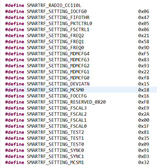
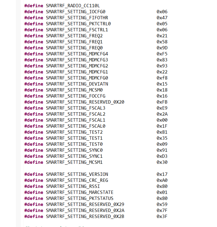
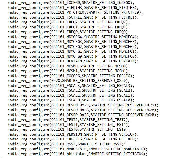
3.CONFIGURING RADIO REGISTER
4.PA table writing
5.sending SFSTXON command
6.giving SNOP command
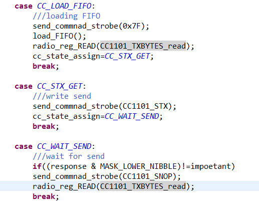
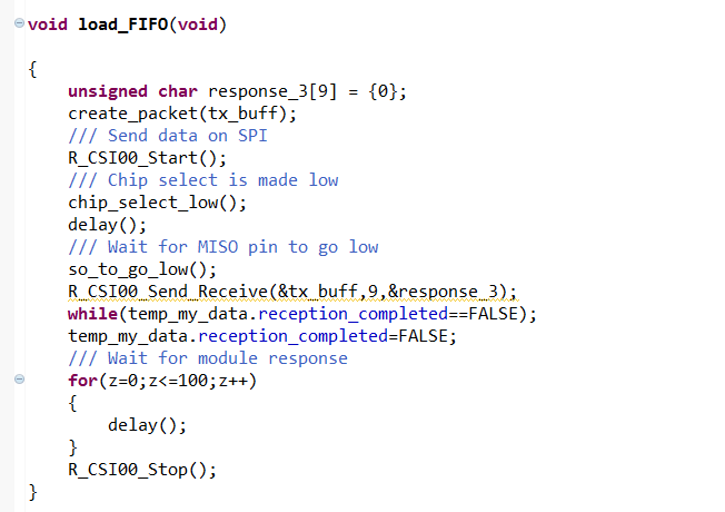
7.loading FIFO
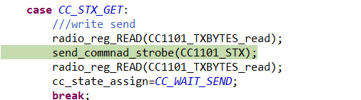
8.sending STX command
i has send my code to you for reference.
/***********************************************************************************************************************
* DISCLAIMER
* This software is supplied by Renesas Electronics Corporation and is only intended for use with Renesas products.
* No other uses are authorized. This software is owned by Renesas Electronics Corporation and is protected under all
* applicable laws, including copyright laws.
* THIS SOFTWARE IS PROVIDED "AS IS" AND RENESAS MAKES NO WARRANTIES REGARDING THIS SOFTWARE, WHETHER EXPRESS, IMPLIED
* OR STATUTORY, INCLUDING BUT NOT LIMITED TO WARRANTIES OF MERCHANTABILITY, FITNESS FOR A PARTICULAR PURPOSE AND
* NON-INFRINGEMENT. ALL SUCH WARRANTIES ARE EXPRESSLY DISCLAIMED.TO THE MAXIMUM EXTENT PERMITTED NOT PROHIBITED BY
* LAW, NEITHER RENESAS ELECTRONICS CORPORATION NOR ANY OF ITS AFFILIATED COMPANIES SHALL BE LIABLE FOR ANY DIRECT,
* INDIRECT, SPECIAL, INCIDENTAL OR CONSEQUENTIAL DAMAGES FOR ANY REASON RELATED TO THIS SOFTWARE, EVEN IF RENESAS OR
* ITS AFFILIATES HAVE BEEN ADVISED OF THE POSSIBILITY OF SUCH DAMAGES.
* Renesas reserves the right, without notice, to make changes to this software and to discontinue the availability
* of this software. By using this software, you agree to the additional terms and conditions found by accessing the
* following link:
* http://www.renesas.com/disclaimer
*
* Copyright (C) 2011, 2018 Renesas Electronics Corporation. All rights reserved.
***********************************************************************************************************************/
/***********************************************************************************************************************
* File Name : r_main.c
* Version : CodeGenerator for RL78/G12 V2.04.02.04 [18 May 2018]
* Device(s) : R5F1026A
* Tool-Chain : CCRL
* Description : This file implements main function.
* Creation Date: 20-05-2019
***********************************************************************************************************************/
/***********************************************************************************************************************
Includes
***********************************************************************************************************************/
#include "r_cg_macrodriver.h"
#include "r_cg_cgc.h"
#include "r_cg_port.h"
#include "r_cg_serial.h"
/* Start user code for include. Do not edit comment generated here */
/* End user code. Do not edit comment generated here */
#include "r_cg_userdefine.h"
/***********************************************************************************************************************
Pragma directive
***********************************************************************************************************************/
/* Start user code for pragma. Do not edit comment generated here */
/* End user code. Do not edit comment generated here */
/***********************************************************************************************************************
Global variables and functions
***********************************************************************************************************************/
/* Start user code for global. Do not edit comment generated here */
void delay(void);
void chip_select_low(void);
void chip_select_high(void);
void so_to_go_low(void);
void send_commnad_strobe(unsigned char);
void configure_cc110l_register(void);
void CC1101_Control_task(void);
void radio_reg_configure(unsigned char,unsigned char);
void whole_configuration(void);
void CC11XX_WritePatable(void);
void create_packet(uint8_t tx_buff[]);
void load_FIFO(void);
void CC1101_Initalization(void);
void radio_reg_READ(unsigned char);
uint8_t response,RESP_SRES_SIDLE=0x0F;
uint8_t z,brust_data=0x40;
uint8_t paTable[3]={0},BURST_DATA=0x40,PKTLEN=0x06,your_gate=0x05;
uint8_t MASK_LOWER_NIBBLE=0xf0,STATE_SFSTX=0x30,WRITE_STROBE=0x00;
uint8_t tx_buff[6];
uint8_t wait,retry_count;
struct my_data
{
unsigned volatile char trnas_comleted :1;
unsigned volatile char reception_completed :1;
}temp_my_data;
typedef enum cc_state_enum
{
/// Resets chip
CC_INIT_RESET,
/// Configuration of radio
CC_RADIO_CFG,
/// Frequency Synthesizing
CC_SFSTXON_TX,
/// Get the status byte of the chip
CC_SNOP_TX,
/// Load data in FIFO
CC_LOAD_FIFO,
/// Transmit the data on Air
CC_STX,
/// Transition delay between state change
CC11XX_WAIT_FOR_SEND,
/// Flush TX FIFO condition
CC_SFTX
} cc_state_enum;
cc_state_enum cc_state_assign;
/* End user code. Do not edit comment generated here */
void R_MAIN_UserInit(void);
/***********************************************************************************************************************
* Function Name: main
* Description : This function implements main function.
* Arguments : None
* Return Value : None
***********************************************************************************************************************/
void main(void)
{
R_MAIN_UserInit();
/* Start user code. Do not edit comment generated here */
/* End user code. Do not edit comment generated here */
}
/***********************************************************************************************************************
* Function Name: R_MAIN_UserInit
* Description : This function adds user code before implementing main function.
* Arguments : None
* Return Value : None
***********************************************************************************************************************/
void R_MAIN_UserInit(void)
{
/* Start user code. Do not edit comment generated here */
EI();
CC1101_Initalization();
while (1)
{
CC1101_Control_task();
}
/* End user code. Do not edit comment generated here */
}
/* Start user code for adding. Do not edit comment generated here */
void CC1101_Initalization(void)
{
chip_select_high();
cc_state_assign=CC_INIT_RESET;
temp_my_data.trnas_comleted=FALSE;
temp_my_data.reception_completed=FALSE;
}
void CC1101_Control_task(void)
{
switch(cc_state_assign)
{
case CC_INIT_RESET:
/// Reset CC110L chip
send_commnad_strobe(CC1101_SRES);
if(RESP_SRES_SIDLE==response)
{
cc_state_assign=CC_RADIO_CFG;
}
break;
case CC_RADIO_CFG:
/// Puts the chip in SIDLE
send_commnad_strobe( CC1101_SIDLE );
/// Configure Radio chip
whole_configuration();
/// Configure PATABLE for gain
CC11XX_WritePatable();
cc_state_assign=CC_SFSTXON_TX;
radio_reg_configure(CC1101_TEST0,SMARTRF_SETTING_TEST0);
break;
case CC_SFSTXON_TX:
///frequency
send_commnad_strobe(CC1101_SFSTXON);
cc_state_assign=CC_SNOP_TX;
break;
case CC_SNOP_TX:
///NO OPERATION
send_commnad_strobe(CC1101_SNOP);
send_commnad_strobe(CC1101_SNOP);
if((response & MASK_LOWER_NIBBLE)==STATE_SFSTX)
{
cc_state_assign=CC_LOAD_FIFO;
}
else
{
if(++retry_count<=5)
{
cc_state_assign=CC_SFSTXON_TX;
}
else
{
retry_count=0;
CC1101_Initalization();
}
}
break;
case CC_LOAD_FIFO:
///loading FIFO
cc_state_assign=CC_STX;
load_FIFO();
break;
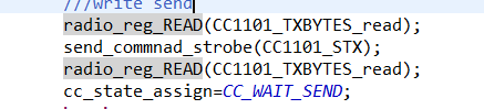
case CC_STX:
///write send
send_commnad_strobe(CC1101_STX);
send_commnad_strobe(CC1101_STX);
cc_state_assign=CC11XX_WAIT_FOR_SEND;
break;
case CC11XX_WAIT_FOR_SEND:
///wait for send
for(wait=0;wait<=250;wait++)
{
delay();
delay();
delay();
delay();
}
cc_state_assign=CC_SFTX;
break;
case CC_SFTX:
///use it
send_commnad_strobe(CC1101_SFTX);
delay();
delay();
CC1101_Initalization();
break;
}
}
void delay(void)
{
unsigned int i;
for(i=0;i<=250;i++);
}
void chip_select_low(void)
{
P1=P1 & (~(0x08));
}
void chip_select_high(void)
{
P1=P1|0x08;
}
void so_to_go_low(void)
{
while(0x02==(P1 & (0x02)));
}
void send_commnad_strobe(unsigned char command)
{
/// Chip select is made low
chip_select_low();
/// Wait for MISO pin to go low
so_to_go_low();
/// Send data on SPI
R_CSI00_Start();
delay();
R_CSI00_Send_Receive(&command,ONE,&response);
while((temp_my_data.trnas_comleted==FALSE) && (temp_my_data.reception_completed==FALSE));
temp_my_data.trnas_comleted=FALSE;
temp_my_data.reception_completed=FALSE;
R_CSI00_Stop();
delay();
/// Wait for module response
for(z=0;z<=200;z++)
{
delay();
delay();
}
}
void radio_reg_configure(unsigned char add,unsigned char valu)
{
unsigned char radio_register[2],radio_response[2]={0};
radio_register[0]=(brust_data|add);
radio_register[1]=valu;
/// Chip select is made low
chip_select_low();
/// Wait for MISO pin to go low
so_to_go_low();
/// Send data on SPI
R_CSI00_Start();
delay();
R_CSI00_Send_Receive(&radio_register,TWO,&radio_response);
while((temp_my_data.trnas_comleted==FALSE) && (temp_my_data.reception_completed==FALSE));
temp_my_data.trnas_comleted=FALSE;
temp_my_data.reception_completed=FALSE;
R_CSI00_Stop();
delay();
chip_select_high();
}
void radio_reg_READ(unsigned char add)
{
unsigned char radio_register[2],radio_response[2]={0};
radio_register[0]=(brust_data|add);
radio_register[1]=0x00;
/// Chip select is made low
chip_select_low();
/// Wait for MISO pin to go low
so_to_go_low();
/// Send data on SPI
R_CSI00_Start();
delay();
R_CSI00_Send_Receive(&radio_register,TWO,&radio_response);
while((temp_my_data.trnas_comleted==FALSE) && (temp_my_data.reception_completed==FALSE));
temp_my_data.trnas_comleted=FALSE;
temp_my_data.reception_completed=FALSE;
R_CSI00_Stop();
delay();
chip_select_high();
}
void whole_configuration(void)
{
radio_reg_configure(CC1101_IOCFG0,SMARTRF_SETTING_IOCFG0);
radio_reg_configure(CC1101_FIFOTHR,SMARTRF_SETTING_FIFOTHR);
radio_reg_configure(CC1101_PKTCTRL0,SMARTRF_SETTING_PKTCTRL0);
radio_reg_configure(CC1101_FSCTRL1,SMARTRF_SETTING_FSCTRL1);
radio_reg_configure(CC1101_FREQ2,SMARTRF_SETTING_FREQ2);
radio_reg_configure(CC1101_FREQ1,SMARTRF_SETTING_FREQ1);
radio_reg_configure(CC1101_FREQ0,SMARTRF_SETTING_FREQ0);
radio_reg_configure(CC1101_MDMCFG4,SMARTRF_SETTING_MDMCFG4);
radio_reg_configure(CC1101_MDMCFG3,SMARTRF_SETTING_MDMCFG3);
radio_reg_configure(CC1101_MDMCFG2,SMARTRF_SETTING_MDMCFG2);
radio_reg_configure(CC1101_MDMCFG1,SMARTRF_SETTING_MDMCFG1);
radio_reg_configure(CC1101_MDMCFG0,SMARTRF_SETTING_MDMCFG0);
radio_reg_configure(CC1101_DEVIATN,SMARTRF_SETTING_DEVIATN);
radio_reg_configure(CC1101_MCSM0,SMARTRF_SETTING_MCSM0);
radio_reg_configure(CC1101_FOCCFG,SMARTRF_SETTING_FOCCFG);
radio_reg_configure(0x20,SMARTRF_SETTING_RESERVED_0X20);
radio_reg_configure(CC1101_FSCAL3,SMARTRF_SETTING_FSCAL3);
radio_reg_configure(CC1101_FSCAL2,SMARTRF_SETTING_FSCAL2);
radio_reg_configure(CC1101_FSCAL1,SMARTRF_SETTING_FSCAL1);
radio_reg_configure(CC1101_FSCAL0,SMARTRF_SETTING_FSCAL0);
radio_reg_configure(CC1101_TEST2,SMARTRF_SETTING_TEST2);
radio_reg_configure(CC1101_TEST1,SMARTRF_SETTING_TEST1);
radio_reg_configure(CC1101_TEST0,SMARTRF_SETTING_TEST0);
radio_reg_READ(CC1101_IOCFG0_read);
radio_reg_READ(CC1101_FIFOTHR_read);
radio_reg_READ(CC1101_PKTCTRL0_read);
radio_reg_READ(CC1101_FSCTRL1_read);
radio_reg_READ(CC1101_FREQ2_read);
radio_reg_READ(CC1101_FREQ1_read);
radio_reg_READ(CC1101_FREQ0_read);
radio_reg_READ(CC1101_MDMCFG4_read);
radio_reg_READ(CC1101_MDMCFG3_read);
radio_reg_READ(CC1101_MDMCFG2_read);
radio_reg_READ(CC1101_MDMCFG1_read);
radio_reg_READ(CC1101_MDMCFG0_read);
radio_reg_READ(CC1101_DEVIATN_read);
radio_reg_READ(CC1101_MCSM0_read);
radio_reg_READ(CC1101_FOCCFG_read);
radio_reg_READ(0x20);
radio_reg_READ(CC1101_FSCAL3_read);
radio_reg_READ(CC1101_FSCAL2_read);
radio_reg_READ(CC1101_FSCAL1_read);
radio_reg_READ(CC1101_FSCAL0_read);
radio_reg_READ(CC1101_TEST2_read);
radio_reg_READ(CC1101_TEST1_read);
radio_reg_READ(CC1101_TEST0_read);
}
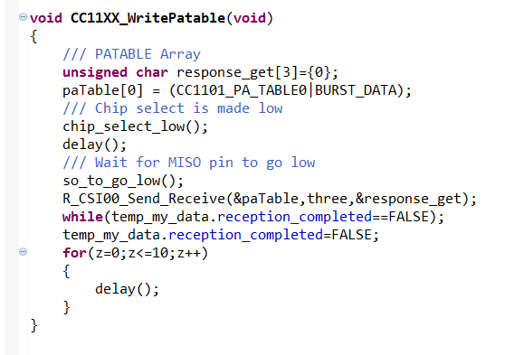
void CC11XX_WritePatable(void)
{
/// PATABLE Array
unsigned char response_get[3]={0};
paTable[0] = CC1101_PA_TABLE0|BURST_DATA ;
/// Chip select is made low
chip_select_low();
/// Wait for MISO pin to go low
so_to_go_low();
/// Send data on SPI
R_CSI00_Start();
delay();
R_CSI00_Send_Receive(&paTable,three,&response_get);
while((temp_my_data.trnas_comleted==FALSE) && (temp_my_data.reception_completed==FALSE));
temp_my_data.trnas_comleted=FALSE;
temp_my_data.reception_completed=FALSE;
R_CSI00_Stop();
delay();
}
void load_FIFO(void)
{
unsigned char response_3[6] = {0};
create_packet(tx_buff);
delay();
/// Chip select is made low
chip_select_low();
/// Wait for MISO pin to go low
so_to_go_low();
/// Send data on SPI
R_CSI00_Start();
delay();
R_CSI00_Send_Receive(&tx_buff,(tx_buff[1]),&response_3);
while((temp_my_data.trnas_comleted==FALSE) && (temp_my_data.reception_completed==FALSE));
temp_my_data.trnas_comleted=FALSE;
temp_my_data.reception_completed=FALSE;
R_CSI00_Stop();
delay();
/// Wait for module response
for(z=0;z<=200;z++)
{
delay();
}
}
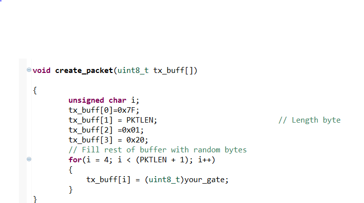
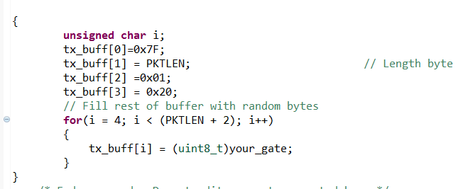
void create_packet(uint8_t tx_buff[])
{
unsigned char p;
tx_buff[0]=(brust_data|WRITE_STROBE|CC1101_FIFO);
tx_buff[1]=PKTLEN;
tx_buff[2]=0x02;
for(p = 3; p < (PKTLEN + 1); p++)
{
tx_buff[p] = (uint8_t)your_gate;
}
}
/* End user code. Do not edit comment generated here */
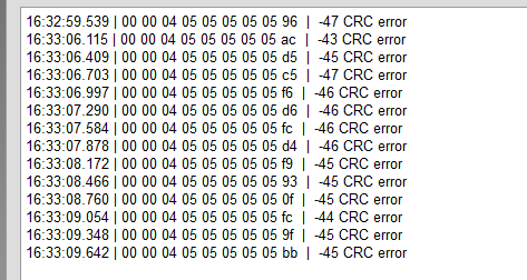
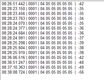
1.step one reset chip. following response i got.

2.sending ideal command.

3 . configuring all register and reading back its value its fine. what i has wrote the same i am reading back.
4.writing PA table.

5. i now want load FIFO but i am unable to load FIFO.
how to solve this problem. please help.