This thread has been locked.

If you have a related question, please click the "Ask a related question" button in the top right corner. The newly created question will be automatically linked to this question.

WL1837MOD: Spurious emission (Rx) test failure during Korean RE testing

Part Number: WL1837MOD
Other Parts Discussed in Thread: WL1837, WL18XXCOM82SDMMC, WL1835MOD, , , WL1835MODCOM8B, WL1835

Hi,

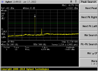
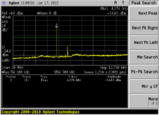
We are trying to run the RE testing for Korean Certification with the WL1837 WIFI module in the WL18XXCOM82SDMMC evaluation board. We have a failure in the Spurious emission (Rx) has -34.63 dBm which is 20 dB above the limit (-54 dBm). The below attached ini file and bin file are being used for the testing. Kindly, advice on solving the issue. The spectrum analyzer image has been attached for reference.

WL1835MOD_INI.ini.txt
#######################################
##      WL1835MOD_INI                ##
#######################################
PHY_StandAlone              	= 00 # Boolean Indicates that there is no MAC cortex active; One of the major impacts is that PHY needs to perform TOP init phase that is done by MAC cortex in operational Mode; 0x0  with Mac; 0x1  no Mac
PrimaryClockSettingTime     	= 05 # Time in millisecond from: Rising PRIMARY_CLK_REQ_OUT(9x)/CLK_REQ_OUT(5x) to valid CLK_IN_PRIMARY_P(9x)/CLK_IN_P(5x) from host 
ClockValidOnWakeUp          	= 00 # [Not Supported]  Indicate that when a host wakeup command is issued to the device a valid reference clock is already valid and stable; 0 - Reference clock is not valid  (Default) 1 - Reference clock is already valid and stable (Fast Sleep)
SecondaryClockSettingTime   	= 05 # 189x Only; Time in millisecond from:Rising SECONDARY_CLK_REQ_OUT to valid CLK_IN_SECONDARY from host (Default 5msec).
Spare0                      	= 08 # [Not Supported]  TI Internal Usage
AutoDetect                  	= 00 # [Not Supported]  0x0 - Disabled; 0x1 - Enabled
Dedicated_FEM               	= 00 # [Not Supported] Bit 0: no FEM Bit 2..3:  vendor options (0: RFMD; 1: TQS; 2: SKWS )
LowBand_component           	= 02 # 0x2: 2way or 3way switch. Other values N/A
LowBand_component_type      	= 05 # 0x5: One Hot 1.8V. Other values N/A
HighBand_component          	= 01 # 0x1: 2way switch. Other values N/A
HighBand_component_type     	= 09 # 0x9: One Hot 3V. Other values N/A
NumberOfAssembledAnt2_4     	= 02 # Indicates the active bands and the number of mounted antennas for 2.4GHz;  
NumberOfAssembledAnt5       	= 01 # Indicates the active bands and the number of mounted antennas for 5GHz;
External_PA_DC2DC           	= 00 # 0: Internal_PA_DC2DC (Default); 1: External_PA_DC2DC
TCXO_LDO_Voltage            	= 00 # TCXO LDO 2V5 voltage level select 0x0: 2.5v;  0x1: 2.55v; 0x2: 2.6v; 
XTALItrimVal                	= 04 # 185x Only; Current trimming for XTAL, (Default) 0x4 
IO_configuration            	= 01 # Configure drive strength of all non-fixed IO's (Detailed in 18xx_PG2_spinner_xls_sheets.xml) according to the following table:0x0 - 8mA.0x1 - 4mA (default).0x2 - 6mA.0x3 - 2mA
SDIO_configuration          	= 00 # [Not Supported] Bit 0: SDIO IB Enable sync; Bit 1: SDIO IB Enable async; Bit 2: SDIO IB Enable BlockMode;
Settings                    	= 00 # [Not Supported] TI internal - General configuration:Bit 0: N/A ;Bit 1: Enable OCLA over SoC 32K PRAM mode
RxProfile                       = 00 # [Not Supported] TI Internal Usage
PwrLimitReference11ABG      	= 64 # Single absolute output power value (dBm) that serves as the baseline for all perChanPwrLimitArrABG. Range 0..25.5dBm, Resolution 0.1dB;
PwrLimitReference11P        	= 64 # Single absolute output power value (dBm) that serves as the baseline for all perChanPwrLimitArr11P. Range 0..25.5dBm, Resolution 0.1dB;
Board_Type                  	= 02 # EVB_18XX = 0; DVP_18XX = 1; HDK_18XX = 2; FPGA_18XX = 3; COM8_18XX = 4;
EnableCLPC                  	= 00 # Boolean that enables the Closed Loop Power Control FW mechanism. In external FEM solution (only 5 GHz), we will monitor and correct the output power based on power detector readings; 0x0  Disabled; 0x1 - Enabled;
EnableTxLowPwrOnSiSoRdl     	= 00 # [Not Supported]  TI Internal Usage
Spare1                      	= 00 # [Not Supported]  TI Internal Usage
PerChanBoMode11ABG             	= 40 00 04 70 00 00 00 00 00 00 00 00 14
#PerChanBoMode11ABG represents a 2 bits per channel array (49 channels, hence 13 bytes used). Channels destribution per byte from left side is as follow:
#Byte0: 1,2,3,4; Byte1: 5,6,7,8; Byte2: 9,10,11,12; Byte3: 13,14,j1,j2; Byte4: j3,j4,j8,j12; Byte5: j16,j34,36,j38; Byte6: 40,j42,44,j46; Byte7: 48,52,56,60; Byte8: 64,100,104,108; Byte9: 112,116,120,124; Byte10: 128,132,136,140; Byte11: 149,153,157,161; Byte12: 165,spare 6 bits for fixed BO cfg
#BackOff Mode coding:
# 0 - BO taken from table per rate (default),  
# 1 - Use MAX[fixed BO, Table BO] for 11n & 11g rates only and apply 200nsec TX windowing. fixed BO is set by PerChanBoMode11ABG[103:100] as follow: [103:102] - Set fixed BO for 11n & 11g in 2.4G case with static BW 20M: 0: 7dB; 1: 9dB; 2: 11dB; 3: 13dB; [101:100] - Set fixed BO for 11n & 11g in 2.4G case with static BW 40M: 0: 7dB; 1: 9dB; 2: 11dB; 3: 13dB; Note: 11b packets uses Table BO, 
# 2 - Same as 1
# 3 - Use MAX[fixed BO, Table BO] for 11n, 11g & 11b rates and apply 200nsec TX windowing. fixed BO is set by PerChanBoMode11ABG[103:98] as follow: [103:102] - Set fixed BO for 11n & 11g in 2.4G case with static BW 20M: 0: 7dB; 1: 9dB; 2: 11dB; 3: 13dB; [101:100] - Set fixed BO for 11n & 11g in 2.4G case with static BW 40M: 0: 7dB; 1: 9dB; 2: 11dB; 3: 13dB; [99:98] - Set fixed BO for 11b: 0: 5dB; 1: 7dB; 2: 9dB; 3: 11dB;
PerChanBoMode11P             	= 00 00 00 00
#PerChanBoMode11P represents a 2 bits per channel array (14 channels, hence 4 bytes used). Channels destribution per byte from left side is as follow:
#Byte0: 171,172,173,174; Byte1: 175,176,177,178; Byte2: 179,180,181,182; Byte3: 183,184,spare 4 bits for fixed BO cfg
#BackOff Mode coding:
# 0 - BO taken from table per rate (default),  
# 1 - Same as 3
# 2 - Same as 3
# 3 - Use MAX[fixed BO, Table BO] for 11n, 11a & 11p rates and apply 200nsec TX windowing. fixed BO is set by PerChanBoMode11P[31:28] as follow: [31:30] - Set fixed BO for 11n & 11g in 5G case with static BW 20M: 0: 7dB; 1: 9dB; 2: 11dB; 3: 13dB; [29:28] - Set fixed BO for 11n & 11g in 5G case with static BW 40M: 0: 7dB; 1: 9dB; 2: 11dB; 3: 13dB; Note: PerChanBoMode11P[31:28] is applicable to both 5G band and 11P band
PinMuxingPlatformOptions    	= 00 00 # [Not Supported]  PinMux options; Byte1 185x (Bit 0: NLE, Bit 1: FM LNA EN); Byte2 189x: (Bit 0: NLE, Bit 1: GPS antenna select, Bit 2: FM LNA EN, Bit 3: GPS PPS OUT, Bit 4: GPS external LNA EN)
PerChanPwrLimitArr11P       	= ff ff ff ff ff ff ff 
# PerChanPwrLimitArr11P Limits the TX output power at each of the 11P channels: 14 channels, 1 nibble per channel.
# PerChanPwrLimitArr11P nibbles: (ch=0),(ch=1),(ch=2),...,(ch=13).
# In each nibble: Value is in delta from the pwrLimitReferenceP(dB). Range 0dB to 15dB. Resolution: 1dB (0,1,...,15dB)
SRState                     	= 00 # [Not Supported] Smart Reflex 0-Disabled, 1 -Enabled 
SRF1                        	= 00 00 00 00 00 00 00 00 00 00 00 00 00 00 00 00 # [Not Supported] Smart Reflex Parameters SRF1 - 1st parameter - num of rows;
SRF2                        	= 00 00 00 00 00 00 00 00 00 00 00 00 00 00 00 00 # [Not Supported] Smart Reflex Parameters SRF2 - 2nd parameter - upper limit of the table;
SRF3                        	= 00 00 00 00 00 00 00 00 00 00 00 00 00 00 00 00 # [Not Supported] Smart Reflex Parameters SRF3 - All other parameters - Table values;
#                                |__CH1___|__CH2___|__CH3___|__CH4___|__CH5___|__CH6___|__CH7___|__CH8___|__CH9___|__CH10__|__CH11__|__CH12__|__CH13__|__CH14__|___j1___|___j2___|___j3___|___j4___|___j8___|__j12___|__j16___|__j34___|___36___|__j38___|___40___|__j42___|___44___|__j46___|___48___|___52___|___56___|___60___|___64___|__100___|__104___|__108___|__112___|__116___|__120___|__124___|__128___|__132___|__136___|__140___|__149___|__153___|__157___|__161___|__165___|_spare__|
PerChanPwrLimitArr11ABG         = ff ff ff ff ff ff ff ff ff ff ff ff ff ff 2f ff ff ff ff ff f2 ff ff ff ff ff ff ff ff ff ff ff ff ff ff ff ff ff ff ff ff ff ff ff ff ff ff ff ff ff ff ff ff ff ff ff ff ff ff ff ff ff ff ff ff ff ff ff ff ff ff ff ff ff ff ff ff ff ff ff ff ff ff ff ff ff ff ff ff ff ff ff ff ff ff ff ff ff ff ff ff ff ff ff ff ff ff ff ff ff ff ff ff ff ff ff ff ff ff ff ff ff ff ff ff ff ff ff ff ff ff ff ff ff ff ff ff ff ff ff ff ff ff ff ff ff ff ff ff ff
# PerChanPwrLimitArr11ABG Limits the TX output power at each of the 11ABG channels. 49 channels, 6 nibbles (= 3 bytes) per channel, nibble per each one of 6 modulation types at each channel.
# PerChanPwrLimitArr11ABG nibbles: (ch=0,mod=0),(ch=0,mod=1),(ch=0,mod=2),...,(ch=0,mod=5),(ch=1,mod=0),...,(ch=48,mod=5).
# In each nibble: Value is in delta from the pwrLimitReferenceABG(dB). Range is 0dB to 15dB. Resolution: 1dB (0,1,...,15dB)
PsatMode                    	= 00 # [Not Supported]  TI Internal Usage
#Following three params are For Dynamic Tx Power level control in operational mode STA HP BG only:
TxPower_level_MaxPower      	= ff # Max Tx power level   ; (Auto mode power setting - 0xff(default mode); Manual mode power settings  - 0..30dBm (Default = 0x18 = 24dbm = max power at BG1)
TxPower_level_MedPower       	= ff # Medium Tx power level; (Auto mode power setting - 0xff(default mode); Manual mode power settings  - 0..30dBm (Default = 0x12 = 18dBm = value for optimal CC) i.e. In case of PerSubBandTxTraceLoss different from 0, TxPower_level_MedPower = 0x12dBm-PerSubBandTxTraceLoss[BG2]
TxPower_level_LowPower      	= ff # Low Tx power level   ; (Auto mode power setting - 0xff(default mode); Manual mode power settings  - 0..30dBm (Default = 0x08 = 8dBm = for best link condition)
#                                | BG  |       A Tx-1          |
#                                |B1|B2|A0|A1|A2|A3|A4|A5|A6|A7|
PerSubBandTxTraceLoss           = 10 18 00 00 00 00 00 00 00 00
# Trace Loss value, 10 bytes (0 - BG1, 1 - BG2, 2..9 - A bands). Byte signed Value in Hex. Range -16..15.875dB, Resolution 0.125dB. This parameter is used in the TX calculations;
#                                | BG  |       A RX-1          |      Reserved         |
#                                |B1|B2|A0|A1|A2|A3|A4|A5|A6|A7|      Reserved		   |
PerSubBandRxTraceLoss           = 10 18 00 00 00 00 00 00 00 00 00 00 00 00 00 00 00 00 
# Trace Loss value, 18 bytes (0 - BG1, 1 - BG2, 2..9 - RX1 A bands, 10..17 - RX2 A bands). Byte signed Value in Hex. Range -16..15.875dB, Resolution 0.125dB. This parameter is used in RX RSSI at ant point report;
TxRfMargin                  	= 01 # Indicates the commited EVM/Mask margin in dB: 0,1,2,3 or 4. Default = 1;
TxPower_level_MaxPower_2nd      = ff # For Dynamic Tx Power level control in operational mode non STA HP BG, Max Tx power level in dBm Hex val 0..30; (Default = 0x14 - max BG2)
TxPower_level_MedPower_2nd      = ff # For Dynamic Tx Power level control in operational mode non STA HP BG, Medium Tx power level; (Default = 0x0A- med BG2)
TxPower_level_LowPower_2nd      = ff # For Dynamic Tx Power level control in operational mode non STA HP BG, Low Tx power level; (Default = 0x05- low BG2)
wl18xx-fw-4.bin.txt

Regards,

Sudar

  • Hi Sudar,

    If you are using the WL1837MOD, you should be using the INI titled "WL1837MOD_INI_FCC_CE_JP".

    BR,

    Seong

  • Hi Seong,

    We tried the "WL1837MOD_INI_FCC_CE_JP" and we got some improvements around 4 db but still the failure spurious emission for Rx with 16 dB above the limit (-54 dBm) . Kindly, let us know what needs to be done further to solve this issue.

    WL1837MOD_INI_FCC_CE_JP.ini.txt
    #######################################
    ##      WL8_1837_TI_module_INI       ##
    #######################################


    PHY_StandAlone              	= 00 # Boolean Indicates that there is no MAC cortex active; One of the major impacts is that PHY needs to perform TOP init phase that is done by MAC cortex in operational Mode; 0x0  with Mac; 0x1  no Mac
    PrimaryClockSettingTime     	= 05 # Time in millisecond from: Rising PRIMARY_CLK_REQ_OUT(9x)/CLK_REQ_OUT(5x) to valid CLK_IN_PRIMARY_P(9x)/CLK_IN_P(5x) from host 
    ClockValidOnWakeUp          	= 00 # [Not Supported]  Indicate that when a host wakeup command is issued to the device a valid reference clock is already valid and stable; 0 - Reference clock is not valid  (Default) 1 - Reference clock is already valid and stable (Fast Sleep)
    SecondaryClockSettingTime   	= 05 # 189x Only; Time in millisecond from:Rising SECONDARY_CLK_REQ_OUT to valid CLK_IN_SECONDARY from host (Default 5msec).
    Spare0                      	= 08 # [Not Supported]  TI Internal Usage
    AutoDetect                  	= 00 # [Not Supported]  0x0 - Disabled; 0x1 - Enabled
    Dedicated_FEM               	= 00 # [Not Supported] Bit 0: no FEM Bit 2..3:  vendor options (0: RFMD; 1: TQS; 2: SKWS )
    LowBand_component           	= 02 # 0x2: 2way or 3way switch. Other values N/A
    LowBand_component_type      	= 05 # 0x5: One Hot 1.8V. Other values N/A
    HighBand_component          	= 01 # 0x1: 2way switch. Other values N/A
    HighBand_component_type     	= 0A # 0x9: One Hot 3V. Other values N/A
    NumberOfAssembledAnt2_4     	= 02 # Indicates the active bands and the number of mounted antennas for 2.4GHz;  
    NumberOfAssembledAnt5       	= 01 # Indicates the active bands and the number of mounted antennas for 5GHz;
    External_PA_DC2DC           	= 00 # 0: Internal_PA_DC2DC (Default); 1: External_PA_DC2DC
    TCXO_LDO_Voltage            	= 00 # TCXO LDO 2V5 voltage level select 0x0: 2.5v;  0x1: 2.55v; 0x2: 2.6v; 
    XTALItrimVal                	= 04 # 185x Only; Current trimming for XTAL, (Default) 0x4 
    IO_configuration            	= 01 # Configure drive strength of all non-fixed IO's (Detailed in 18xx_PG2_spinner_xls_sheets.xml) according to the following table:0x0 - 8mA.0x1 - 4mA (default).0x2 - 6mA.0x3 - 2mA
    SDIO_configuration          	= 00 # [Not Supported] Bit 0: SDIO IB Enable sync; Bit 1: SDIO IB Enable async; Bit 2: SDIO IB Enable BlockMode;
    Settings                    	= 00 # [Not Supported] TI internal - General configuration:Bit 0: N/A ;Bit 1: Enable OCLA over SoC 32K PRAM mode
    RxProfile                       = 00 # [Not Supported] TI Internal Usage
    PwrLimitReference11ABG      	= 55 # Single absolute output power value (dBm) that serves as the baseline for all perChanPwrLimitArrABG. Range 0..25.5dBm, Resolution 0.1dB;
    PwrLimitReference11P        	= 64 # Single absolute output power value (dBm) that serves as the baseline for all perChanPwrLimitArr11P. Range 0..25.5dBm, Resolution 0.1dB;
    Board_Type                  	= 02 # EVB_18XX = 0; DVP_18XX = 1; HDK_18XX = 2; FPGA_18XX = 3; COM8_18XX = 4;
    EnableCLPC                  	= 00 # Boolean that enables the Closed Loop Power Control FW mechanism. In external FEM solution (only 5 GHz), we will monitor and correct the output power based on power detector readings; 0x0  Disabled; 0x1 - Enabled;
    EnableTxLowPwrOnSiSoRdl     	= 00 # [Not Supported]  TI Internal Usage
    Spare1                      	= 00 # [Not Supported]  TI Internal Usage
    
    PerChanBoMode11ABG             	= 40 00 04 30 00 00 00 00 00 00 00 40 19 
    #PerChanBoMode11ABG represents a 2 bits per channel array (49 channels, hence 13 bytes used). Channels destribution per byte from left side is as follow:
    #Byte0: 1,2,3,4; Byte1: 5,6,7,8; Byte2: 9,10,11,12; Byte3: 13,14,j1,j2; Byte4: j3,j4,j8,j12; Byte5: j16,j34,36,j38; Byte6: 40,j42,44,j46; Byte7: 48,52,56,60; Byte8: 64,100,104,108; Byte9: 112,116,120,124; Byte10: 128,132,136,140; Byte11: 149,153,157,161; Byte12: 165,spare 6 bits for fixed BO cfg
    #BackOff Mode coding:
    # 0 - BO taken from table per rate (default),  
    # 1 - Use MAX[fixed BO, Table BO] for 11n & 11g rates only and apply 200nsec TX windowing. fixed BO is set by PerChanBoMode11ABG[103:100] as follow: [103:102] - Set fixed BO for 11n & 11g in 2.4G case with static BW 20M: 0: 7dB; 1: 9dB; 2: 11dB; 3: 13dB; [101:100] - Set fixed BO for 11n & 11g in 2.4G case with static BW 40M: 0: 7dB; 1: 9dB; 2: 11dB; 3: 13dB; Note: 11b packets uses Table BO, 
    # 2 - Same as 1
    # 3 - Use MAX[fixed BO, Table BO] for 11n, 11g & 11b rates and apply 200nsec TX windowing. fixed BO is set by PerChanBoMode11ABG[103:98] as follow: [103:102] - Set fixed BO for 11n & 11g in 2.4G case with static BW 20M: 0: 7dB; 1: 9dB; 2: 11dB; 3: 13dB; [101:100] - Set fixed BO for 11n & 11g in 2.4G case with static BW 40M: 0: 7dB; 1: 9dB; 2: 11dB; 3: 13dB; [99:98] - Set fixed BO for 11b: 0: 5dB; 1: 7dB; 2: 9dB; 3: 11dB;
    
    PerChanBoMode11P             	= 00 00 00 01
    #PerChanBoMode11P represents a 2 bits per channel array (14 channels, hence 4 bytes used). Channels destribution per byte from left side is as follow:
    #Byte0: 171,172,173,174; Byte1: 175,176,177,178; Byte2: 179,180,181,182; Byte3: 183,184,spare 4 bits for fixed BO cfg
    #BackOff Mode coding:
    # 0 - BO taken from table per rate (default),  
    # 1 - Same as 3
    # 2 - Same as 3
    # 3 - Use MAX[fixed BO, Table BO] for 11n, 11a & 11p rates and apply 200nsec TX windowing. fixed BO is set by PerChanBoMode11P[31:28] as follow: [31:30] - Set fixed BO for 11n & 11g in 5G case with static BW 20M: 0: 7dB; 1: 9dB; 2: 11dB; 3: 13dB; [29:28] - Set fixed BO for 11n & 11g in 5G case with static BW 40M: 0: 7dB; 1: 9dB; 2: 11dB; 3: 13dB; Note: PerChanBoMode11P[31:28] is applicable to both 5G band and 11P band


    PinMuxingPlatformOptions    	= 00 00 # [Not Supported]  PinMux options; Byte1 185x (Bit 0: NLE, Bit 1: FM LNA EN); Byte2 189x: (Bit 0: NLE, Bit 1: GPS antenna select, Bit 2: FM LNA EN, Bit 3: GPS PPS OUT, Bit 4: GPS external LNA EN)
    
    PerChanPwrLimitArr11P       	= ff ff ff ff ff ff ff 
    # PerChanPwrLimitArr11P Limits the TX output power at each of the 11P channels: 14 channels, 1 nibble per channel.
    # PerChanPwrLimitArr11P nibbles: (ch=0),(ch=1),(ch=2),...,(ch=13).
    # In each nibble: Value is in delta from the pwrLimitReferenceP(dB). Range 0dB to 15dB. Resolution: 1dB (0,1,...,15dB)
    
    SRState                     	= 00 # [Not Supported] Smart Reflex 0-Disabled, 1 -Enabled 
    SRF1                        	= 00 00 00 00 00 00 00 00 00 00 00 00 00 00 00 00 # [Not Supported] Smart Reflex Parameters SRF1 - 1st parameter - num of rows;
    SRF2                        	= 00 00 00 00 00 00 00 00 00 00 00 00 00 00 00 00 # [Not Supported] Smart Reflex Parameters SRF2 - 2nd parameter - upper limit of the table;
    SRF3                        	= 00 00 00 00 00 00 00 00 00 00 00 00 00 00 00 00 # [Not Supported] Smart Reflex Parameters SRF3 - All other parameters - Table values;
    
    
    #                                |__CH1___|__CH2___|__CH3___|__CH4___|__CH5___|__CH6___|__CH7___|__CH8___|__CH9___|__CH10__|__CH11__|__CH12__|__CH13__|__CH14__|___j1___|___j2___|___j3___|___j4___|___j8___|__j12___|__j16___|__j34___|___36___|__j38___|___40___|__j42___|___44___|__j46___|___48___|___52___|___56___|___60___|___64___|__100___|__104___|__108___|__112___|__116___|__120___|__124___|__128___|__132___|__136___|__140___|__149___|__153___|__157___|__161___|__165___|_spare__|
    PerChanPwrLimitArr11ABG  =	      78 88 88 78 88 88 78 88 88 78 88 88 78 88 18 78 88 88 78 88 82 78 88 88 78 88 88 78 88 88 78 88 88 78 88 88 78 88 88 FF FF FF F8 FF FF F8 FF FF F8 FF FF F8 FF FF FF FF FF FF FF FF FF FF FF FF FF FF F7 22 22 FF FF FF F7 22 22 FF FF FF F7 66 66 FF FF FF F7 66 66 F4 44 55 F4 44 55 F4 22 22 F4 22 22 F6 44 44 FF 44 44 F7 66 66 F7 66 66 F7 66 66 F7 66 66 F7 66 66 F7 66 66 F7 66 55 F7 44 55 F4 FF FF FF 33 22 FF 33 22 FF 66 66 FF 44 66 F6 FF FF FF FF FF 
    
    
    # PerChanPwrLimitArr11ABG Limits the TX output power at each of the 11ABG channels. 49 channels, 6 nibbles (= 3 bytes) per channel, nibble per each one of 6 modulation types at each channel.
    # PerChanPwrLimitArr11ABG nibbles: (ch=0,mod=0),(ch=0,mod=1),(ch=0,mod=2),...,(ch=0,mod=5),(ch=1,mod=0),...,(ch=48,mod=5).
    # In each nibble: Value is in delta from the pwrLimitReferenceABG(dB). Range is 0dB to 15dB. Resolution: 1dB (0,1,...,15dB)
    
    PsatMode                    	= 00 # [Not Supported]  TI Internal Usage
    
    #Following three params are For Dynamic Tx Power level control in operational mode STA HP BG only:
    TxPower_level_MaxPower      	= ff # Max Tx power level   ; (Auto mode power setting - 0xff(default mode); Manual mode power settings  - 0..30dBm (Default = 0x18 = 24dbm = max power at BG1)
    TxPower_level_MedPower       	= ff # Medium Tx power level; (Auto mode power setting - 0xff(default mode); Manual mode power settings  - 0..30dBm (Default = 0x12 = 18dBm = value for optimal CC) i.e. In case of PerSubBandTxTraceLoss different from 0, TxPower_level_MedPower = 0x12dBm-PerSubBandTxTraceLoss[BG2]
    TxPower_level_LowPower      	= ff # Low Tx power level   ; (Auto mode power setting - 0xff(default mode); Manual mode power settings  - 0..30dBm (Default = 0x08 = 8dBm = for best link condition)


    #                                | BG  |       A Tx-1          |
    #                                |B1|B2|A0|A1|A2|A3|A4|A5|A6|A7|
    PerSubBandTxTraceLoss           = 08 18 10 10 10 10 10 10 10 10
    # Trace Loss value, 10 bytes (0 - BG1, 1 - BG2, 2..9 - A bands). Byte signed Value in Hex. Range -16..15.875dB, Resolution 0.125dB. This parameter is used in the TX calculations;
    
    #                                | BG  |       A RX-1          |       Reserved          |
    #                                |B1|B2|A0|A1|A2|A3|A4|A5|A6|A7|			 |
    PerSubBandRxTraceLoss           = 08 18 10 10 10 10 10 10 10 10 00 00 00 00 00 00 00 00 
    # Trace Loss value, 18 bytes (0 - BG1, 1 - BG2, 2..9 - RX1 A bands, 10..17 - RX2 A bands). Byte signed Value in Hex. Range -16..15.875dB, Resolution 0.125dB. This parameter is used in RX RSSI at ant point report;
    
    TxRfMargin                  	= 01 # Indicates the commited EVM/Mask margin in dB: 0,1,2,3 or 4. Default = 1;
    
    TxPower_level_MaxPower_2nd      = ff # For Dynamic Tx Power level control in operational mode non STA HP BG, Max Tx power level in dBm Hex val 0..30; (Default = 0x14 - max BG2)
    TxPower_level_MedPower_2nd      = ff # For Dynamic Tx Power level control in operational mode non STA HP BG, Medium Tx power level; (Default = 0x0A- med BG2)
    TxPower_level_LowPower_2nd      = ff # For Dynamic Tx Power level control in operational mode non STA HP BG, Low Tx power level; (Default = 0x05- low BG2)
    

    Regards,

    Sudar.K.B.

  • Sudar,

    Thanks for testing and sharing the test results. I will look into this further and get back to you.

    BR,

    Seong

  • Seong,

    Any update for us on the above mentioned observation??

    Regards,

    Sudar

  • Hi Sudar,

    Yes, we've found what the issue is. We'll need to make some updates to the the FW to fix this. This effort may take up to two weeks. Apologies for the inconvenience. I'll keep you posted.

    BR,

    Seong

  • Sudar,

    Which FW version are you using?

    BR,

    Seong

  • Seong,

    The FW version which we are using is 8.9.0.0.79. We have attached the fw binary file (wl18xx-fw-4.bin.txt) in the original post.

    sudar@Sudar-LP:~/Downloads$ strings wl18xx-fw-4.bin.txt | grep -i Rev
    FRev 8.9.0.0.79
    FRev 8.2.0.0.242
    28883,924,acl_role.c,acl_role_SetACLLinkType,2|current link type is ENUM(acl_role_linkType_e,%d), previous link type is ENUM(acl_role_linkType_e,%d)
    1088649,4123,roles.c,Roles_isTwinRoleAllowed,2|is TWIN role allowed ? lRoleDB.db[prevStartedRole].channelNumber = %d, lRoleDB.db[startedRole].channelNumber=%d 
    1088665,4130,roles.c,Roles_isTwinRoleAllowed,3|is TWIN role allowed ? TWIN Role %d , prevStartedRole = %d, startedRole=%d 
    107451,636,scheduler_time_allocation.c,SCHED_TimeAlloc_AllocFreeTime,4|***ERROR (3/4): allocation failure:  prev t_start 0x%8.8x, w_size %d, next t_start 0x%8.8x, delta_1 %d
    119785,46,release.c,PrintRevision,0|Firmware Revision (FRev) Rev 8.9.0.0.79
    74747,173,scheduler_req_list.c,SCHED_Req_List_InsertAfter|prev_req < 22
    74875,253,scheduler_req_list.c,SCHED_Req_List_InsertAfter|p_req->chain_info.prev != req
    74893,410,scheduler_req_list.c,SCHED_Req_List_ComapreByReversedPriority|p_req_1 != p_req_2
    75001,483,scheduler_req_list.c,SCHED_Req_List_InsertByDesignatedCompare|p_req->chain_info.prev == 0xFF
    75089,549,scheduler_req_list.c,SCHED_Req_List_InsertByDesignatedCompare|req != prev_req
    114439,163,scheduler_request_pool.c,SCHED_ReqPool_Free|p_req->chain_info.prev == 0xFF
    DecMgrCmd_e|DECISION_MANAGER_COMMAND_PREVENT_WLAN_TX,0;DECISION_MANAGER_COMMAND_ALLOW_WLAN_TX,1;DECISION_MANAGER_COMMAND_2,2;SUSPEND_TRIGGER_ENABLED_AC,3;RESUME_TRIGGER_ENABLED_AC,4;DECISION_MANAGER_COMMAND_5,5;DECISION_MANAGER_COMMAND_6,6;DECISION_MANAGER_COMMAND_7,7;TRIGGER_ACL_ROLE_SWI,8
    TimerEventType_e|ADD_TIMER,0;ADD_TIMER_FOR_KLV_FRAME,1;UPDATE_TIMER,2;RESTART_TIMER,3
    

    Regards,

    Sudar

  • Hi Sudar,

    Please try using the latest FW, which is version 8.9.0.0.89.

    Please describe the test set up as well. If this is a conducted measurement, is an attenuator used?

    BR,

    Seong

  • Hi Seong,

    We still face the failure in spurious emission for Rx. We dont use an external attenuator.

    camkorea_test method_220216.xlsx

    Kindly, let us know if any other details are required.

    Regards,
    Sudar.K.B.

  • Hi Sudar,

    Will let you know. Please bear with me.

    Thanks,

    Seong

  • Hi Seong,

    Any update on the above request.

    Thanks,

    Sudar

  • Sudar,

    We are in the process of troubleshooting this.

    BR,

    Seong

  • Seong,

    Please let us know if you had any improvements. We have a customer who is waiting on this for his product certification. Kindly, let us know if you would require any further details or any tests or evaluations that can be done at our end.

    Regards,
    Sudar

  • Hi Sudar,

    We are still working on this. I will give you an update by the end of the week and will let you know if I need anything from you. 

    Thanks and best regards,

    Seong

  • Hi Sudar K B,

    Try changing the the following parameter to 02:

    NumberOfAssembledAnt5       	= 02

    BR,

    Seong

  • Hi Seong,

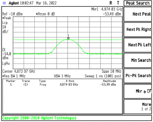
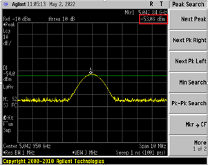
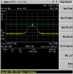
    We did the changes in the INI file and the results got better compared to previous suggestions but it wasn't enough to pass the test. The measured value was -53.49 db which is about 0.5 db above the limits. Previously, the results were at -38.42 db. The current test result image is shared below.

    Regards,
    Sudar

  • Sudar,

    Okay we are close. Will get back to you again soon. 

    BR,

    Seong

  • Sudar,

    Please correct me if I'm wrong, but isn't the limit for KCC RX spurious emissions -47dBm/1MHz for frequencies 1GHz and above?

    BR,

    Seong

  • Seong,

    Yes, limit is -47 dBm for above 1 GHz (bandwidth 1 MHz), and -54 dBm for below  1 GHz (bandwidth 100 kHz).

    Regards,
    Sudar

  • Hi Sudar,

    Seong is under the weather and out of the office today. He will follow-up on this as soon as he can when he is back.

    Best Regards,

    Ben M

  • Hi Ben / Seong,

    I wish Seong a speedy recovery. Please, do share any update if available as we are so close to finding the solution.

    Regards,
    Sudar

  • Hi Sudar,

    Exactly which channel or channels must be tested for this KCC Conducted RX Spurious Emissions Test?

    BR,

    Seong

  • Hi Seong,

    Please find the details requested above.

    Test Mode

     Frequency (WLAN Channel no.)

    Bluetooth(BDR,EDR)

    2402 MHz

    2441 MHz

    2480 MHz

    -

    Bluetooth(BLE)

    2402 MHz

    2440 MHz

    2480 MHz

    -

    WLAN(2.4GHz band)

    2412 MHz (CH1)

    2442 MHz (CH7)

    2472 MHz (CH13)

    -

    WLAN(5.15~5.35GHz band)

    5180 MHz (CH36)

    5240 MHz (CH48)

    5260 MHz (CH52)

    5320 MHz (CH64)

    WLAN(5.47~5.85GHz band)

    5500 MHz (CH100)

    5660 MHz (CH132)

    5825 MHz (CH165)

    -

    Regards,
    Sudar

  • Hi Sudar,

    Thank you for sharing this information. Please follow the following instructions for the Wi-Fi 2.4GHz Rx spurious emission test.

    1. After connecting the EUT to RTTT and loading the FW, open LuaShell by clicking View -> LuaShell.
    2. Enter the following commands in the LuaShell window before starting the RX Spurious Emissions test:
      • ts18.API_SetAntennaMode_24G (1, 1, 0, 0, 1, 1)
      • ts18.API_ChannelTune (0, X, 3)
        • Replace X with the Channel number to test; 1, 7, or 13.
    3. Click on the RX tab on RTTT
    4. Click on "Statistics Mode" to put the device in RX mode.

    No additional inputs to the GUI are needed. 

    Hope this helps,

    Seong

  • Hi Seong,

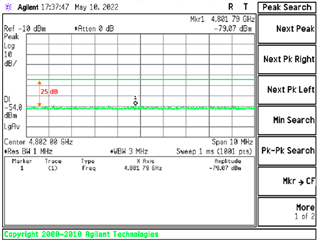
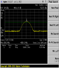
    We followed the instructions mentioned above and still fail with almost same result.

    Fail result on Rx spurious emission test (Limit: -54 dBm, Measured: -53.08 dBm).

    Please, advice on the same.

    Regards,
    Sudar

  • Sudar,

    After following the instructions exactly, did you apply any additional inputs to the GUI?

    Is the NumberofAssembledAnt5 still set to 02 in your INI?

    Were any other modifications made to the default WL1837MOD_INI_FCC_CE_JP.ini? 

    What level is the noise floor at? It is advised to configure the sensitivity of the spectrum analyzer so that the noise floor is at least 12 dB below the -54dBm limit.

    BR,

    Seong

  • Hi Seong,

    No, we did not apply any additional inputs to the GUI.

    Yes, we are using the default WL1837MOD_INI_FCC_CE_JP.ini with the NumberofAssembledAnt5 set to 02.

    Our spectrum analyzer (model name: E4440A) used for testing has a noise floor of 25 dB lower than -54 dBm (limit). So, we believe noise level configuration seems to be fine.

    Regards,
    Sudar

  • Hi Sudar,

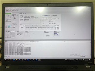
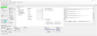
    Could you please share a snapshot of the RTTT GUI when you are observing the -53.08 dB spur?

    BR,

    Seong

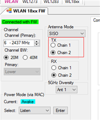
  • Hi Seong,

    The snapshot of the RTTT GUI is shown below.

    Regards,
    Sudar

  • Sudar,

    The snapshot looks like it was taken after the FW is loaded.

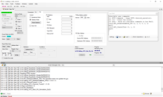
    Please provide a snapshot of the RTTT GUI after completing the previously mentioned steps:

    1. After connecting the EUT to RTTT and loading the FW, open LuaShell by clicking View -> LuaShell.
    2. Enter the following commands in the LuaShell window before starting the RX Spurious Emissions test:
      • ts18.API_SetAntennaMode_24G (1, 1, 0, 0, 1, 1)
      • ts18.API_ChannelTune (0, X, 3)
        • Replace X with the Channel number to test; 1, 7, or 13.
    3. Click on the RX tab on RTTT
    4. Click on "Statistics Mode" to put the device in RX mode.

    BR,

    Seong

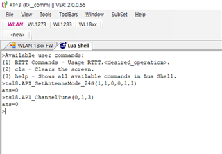
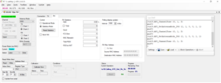
  • Seong,

    Please, find the below image.

    Regards,
    Sudar

  • Sudar,

    Everything looks right. Can you try repeating the test with a WL1837MODCOM8I EVM and see if you are still failing?

    BR,

    Seong

  • Also, is the insertion loss of the cable being used for these measurements being taken into account?

    BR,

    Seong

  • Seong,

    We don't have the WL1837MODCOM8I EVM for our testing.

    Regards,
    Seong

  • Sudar,

    I am able to suppress this down to -58dBm in our lab following the previously provided instructions.

    I am assuming the insertion loss of the cable has been accurately measured and accounted for?

    Lastly, are you measuring RF_ANT1 (pin32) or RF_ANT2 (pin18)?

    BR,

    Seong

  • Seong,

    Yes, the insertion loss of the cable has been measured and accounted. We are measuring from both antennas.

    Regards,
    Sudar

  • Sudar,

    Have you ever requested a design review from this page?

    BR,

    Seongr

  • Hi Seong,

    Please let us know which board design needs to be reviewed? We are using the TI WL18XXCOM82SDMMC evaluation board for our testing here.

    Regards,
    Sudar

  • Sudar,

    You mentioned that you do not have the WL1837MODCOM8I. Does this mean you are interfacing the WL1835MODCOM8B with the WL18XXCOM82SDMMC? If not, what exactly is connected to the WL18XXCOM82SDMMC?

    BR,

    Seong

  • Seong,

    Yes, We are interfacing the WL1835 EVALUATION BOARD with the WL18XXCOM82SDMMC.

    Regards,
    Sudar

  • Sudar K B,

    Are you still using the "WL1837MOD_INI_FCC_CE_JP" INI?

    If you are testing the WL1835MODCOM8B, you should use the "WL1835MOD_INI_C2PC" INI file.

    BR,

    Seong

  • Hi Seong,

    Sorry, there was a little confusion and we seems to have the WL1835 mod board available and we were testing with it.

    We tested with the WL1835MOD_INI_C2PC ini file and we got failure in the ANT2. Please, check the below snapshot.

    ANT1:

    ANT2:

    Is there anything else that needs to be done. We use the below INI file.

    WL18XXMOD_INI_C2PC.txt
    #######################################
    ##    WL8_1835_C2PC_TI_module_INI    ##
    #######################################


    PHY_StandAlone              	= 00 # Boolean Indicates that there is no MAC cortex active; One of the major impacts is that PHY needs to perform TOP init phase that is done by MAC cortex in operational Mode; 0x0  with Mac; 0x1  no Mac
    PrimaryClockSettingTime     	= 05 # Time in millisecond from: Rising PRIMARY_CLK_REQ_OUT(9x)/CLK_REQ_OUT(5x) to valid CLK_IN_PRIMARY_P(9x)/CLK_IN_P(5x) from host 
    ClockValidOnWakeUp          	= 00 # [Not Supported]  Indicate that when a host wakeup command is issued to the device a valid reference clock is already valid and stable; 0 - Reference clock is not valid  (Default) 1 - Reference clock is already valid and stable (Fast Sleep)
    SecondaryClockSettingTime   	= 05 # 189x Only; Time in millisecond from:Rising SECONDARY_CLK_REQ_OUT to valid CLK_IN_SECONDARY from host (Default 5msec).
    Spare0                      	= 08 # [Not Supported]  TI Internal Usage
    AutoDetect                  	= 00 # [Not Supported]  0x0 - Disabled; 0x1 - Enabled
    Dedicated_FEM               	= 00 # [Not Supported] Bit 0: no FEM Bit 2..3:  vendor options (0: RFMD; 1: TQS; 2: SKWS )
    LowBand_component           	= 02 # 0x2: 2way or 3way switch. Other values N/A
    LowBand_component_type      	= 05 # 0x5: One Hot 1.8V. Other values N/A
    HighBand_component          	= 01 # 0x1: 2way switch. Other values N/A
    HighBand_component_type     	= 09 # 0x9: One Hot 3V. Other values N/A
    NumberOfAssembledAnt2_4     	= 02 # Indicates the active bands and the number of mounted antennas for 2.4GHz;  
    NumberOfAssembledAnt5       	= 00 # Indicates the active bands and the number of mounted antennas for 5GHz;
    External_PA_DC2DC           	= 00 # 0: Internal_PA_DC2DC (Default); 1: External_PA_DC2DC
    TCXO_LDO_Voltage            	= 00 # TCXO LDO 2V5 voltage level select 0x0: 2.5v;  0x1: 2.55v; 0x2: 2.6v; 
    XTALItrimVal                	= 04 # 185x Only; Current trimming for XTAL, (Default) 0x4 
    IO_configuration            	= 01 # Configure drive strength of all non-fixed IO's (Detailed in 18xx_PG2_spinner_xls_sheets.xml) according to the following table:0x0 - 8mA.0x1 - 4mA (default).0x2 - 6mA.0x3 - 2mA
    SDIO_configuration          	= 00 # [Not Supported] Bit 0: SDIO IB Enable sync; Bit 1: SDIO IB Enable async; Bit 2: SDIO IB Enable BlockMode;
    Settings                    	= 00 # [Not Supported] TI internal - General configuration:Bit 0: N/A ;Bit 1: Enable OCLA over SoC 32K PRAM mode
    RxProfile                       = 00 # [Not Supported] TI Internal Usage
    PwrLimitReference11ABG      	= 55 # Single absolute output power value (dBm) that serves as the baseline for all perChanPwrLimitArrABG. Range 0..25.5dBm, Resolution 0.1dB;
    PwrLimitReference11P        	= 64 # Single absolute output power value (dBm) that serves as the baseline for all perChanPwrLimitArr11P. Range 0..25.5dBm, Resolution 0.1dB;
    Board_Type                  	= 02 # EVB_18XX = 0; DVP_18XX = 1; HDK_18XX = 2; FPGA_18XX = 3; COM8_18XX = 4;
    EnableCLPC                  	= 00 # Boolean that enables the Closed Loop Power Control FW mechanism. In external FEM solution (only 5 GHz), we will monitor and correct the output power based on power detector readings; 0x0  Disabled; 0x1 - Enabled;
    EnableTxLowPwrOnSiSoRdl     	= 00 # [Not Supported]  TI Internal Usage
    Spare1                      	= 22 # [Not Supported]  TI Internal Usage
    
    PerChanBoMode11ABG             	= 40 00 04 30 00 00 00 00 00 00 00 00 19 
    #PerChanBoMode11ABG represents a 2 bits per channel array (49 channels, hence 13 bytes used). Channels destribution per byte from left side is as follow:
    #Byte0: 1,2,3,4; Byte1: 5,6,7,8; Byte2: 9,10,11,12; Byte3: 13,14,j1,j2; Byte4: j3,j4,j8,j12; Byte5: j16,j34,36,j38; Byte6: 40,j42,44,j46; Byte7: 48,52,56,60; Byte8: 64,100,104,108; Byte9: 112,116,120,124; Byte10: 128,132,136,140; Byte11: 149,153,157,161; Byte12: 165,spare 6 bits for fixed BO cfg
    #BackOff Mode coding:
    # 0 - BO taken from table per rate (default),  
    # 1 - Use MAX[fixed BO, Table BO] for 11n & 11g rates only and apply 200nsec TX windowing. fixed BO is set by PerChanBoMode11ABG[103:100] as follow: [103:102] - Set fixed BO for 11n & 11g in 2.4G case with static BW 20M: 0: 7dB; 1: 9dB; 2: 11dB; 3: 13dB; [101:100] - Set fixed BO for 11n & 11g in 2.4G case with static BW 40M: 0: 7dB; 1: 9dB; 2: 11dB; 3: 13dB; Note: 11b packets uses Table BO, 
    # 2 - Same as 1
    # 3 - Use MAX[fixed BO, Table BO] for 11n, 11g & 11b rates and apply 200nsec TX windowing. fixed BO is set by PerChanBoMode11ABG[103:98] as follow: [103:102] - Set fixed BO for 11n & 11g in 2.4G case with static BW 20M: 0: 7dB; 1: 9dB; 2: 11dB; 3: 13dB; [101:100] - Set fixed BO for 11n & 11g in 2.4G case with static BW 40M: 0: 7dB; 1: 9dB; 2: 11dB; 3: 13dB; [99:98] - Set fixed BO for 11b: 0: 5dB; 1: 7dB; 2: 9dB; 3: 11dB;
    
    PerChanBoMode11P             	= 00 00 00 00
    #PerChanBoMode11P represents a 2 bits per channel array (14 channels, hence 4 bytes used). Channels destribution per byte from left side is as follow:
    #Byte0: 171,172,173,174; Byte1: 175,176,177,178; Byte2: 179,180,181,182; Byte3: 183,184,spare 4 bits for fixed BO cfg
    #BackOff Mode coding:
    # 0 - BO taken from table per rate (default),  
    # 1 - Same as 3
    # 2 - Same as 3
    # 3 - Use MAX[fixed BO, Table BO] for 11n, 11a & 11p rates and apply 200nsec TX windowing. fixed BO is set by PerChanBoMode11P[31:28] as follow: [31:30] - Set fixed BO for 11n & 11g in 5G case with static BW 20M: 0: 7dB; 1: 9dB; 2: 11dB; 3: 13dB; [29:28] - Set fixed BO for 11n & 11g in 5G case with static BW 40M: 0: 7dB; 1: 9dB; 2: 11dB; 3: 13dB; Note: PerChanBoMode11P[31:28] is applicable to both 5G band and 11P band


    PinMuxingPlatformOptions    	= 00 00 # [Not Supported]  PinMux options; Byte1 185x (Bit 0: NLE, Bit 1: FM LNA EN); Byte2 189x: (Bit 0: NLE, Bit 1: GPS antenna select, Bit 2: FM LNA EN, Bit 3: GPS PPS OUT, Bit 4: GPS external LNA EN)
    
    PerChanPwrLimitArr11P       	= ff ff ff ff ff ff ff 
    # PerChanPwrLimitArr11P Limits the TX output power at each of the 11P channels: 14 channels, 1 nibble per channel.
    # PerChanPwrLimitArr11P nibbles: (ch=0),(ch=1),(ch=2),...,(ch=13).
    # In each nibble: Value is in delta from the pwrLimitReferenceP(dB). Range 0dB to 15dB. Resolution: 1dB (0,1,...,15dB)
    
    SRState                     	= 00 # [Not Supported] Smart Reflex 0-Disabled, 1 -Enabled 
    SRF1                        	= 00 00 00 00 00 00 00 00 00 00 00 00 00 00 00 00 # [Not Supported] Smart Reflex Parameters SRF1 - 1st parameter - num of rows;
    SRF2                        	= 00 00 00 00 00 00 00 00 00 00 00 00 00 00 00 00 # [Not Supported] Smart Reflex Parameters SRF2 - 2nd parameter - upper limit of the table;
    SRF3                        	= 00 00 00 00 00 00 00 00 00 00 00 00 00 00 00 00 # [Not Supported] Smart Reflex Parameters SRF3 - All other parameters - Table values;
    
    
    #                                |__CH1___|__CH2___|__CH3___|__CH4___|__CH5___|__CH6___|__CH7___|__CH8___|__CH9___|__CH10__|__CH11__|__CH12__|__CH13__|__CH14__|___j1___|___j2___|___j3___|___j4___|___j8___|__j12___|__j16___|__j34___|___36___|__j38___|___40___|__j42___|___44___|__j46___|___48___|___52___|___56___|___60___|___64___|__100___|__104___|__108___|__112___|__116___|__120___|__124___|__128___|__132___|__136___|__140___|__149___|__153___|__157___|__161___|__165___|_spare__|
    PerChanPwrLimitArr11ABG         = 78 88 88 78 88 88 78 88 88 78 88 88 78 88 18 78 88 88 78 88 82 78 88 88 78 88 88 78 88 88 78 88 88 78 88 88 78 88 88 FF FF FF ff ff ff ff ff ff ff ff ff ff ff ff ff ff ff ff ff ff ff ff ff ff ff ff ff ff ff ff ff ff ff ff ff ff ff ff ff ff ff ff ff ff ff ff ff ff ff ff ff ff ff ff ff ff ff ff ff ff ff ff ff ff ff ff ff ff ff ff ff ff ff ff ff ff ff ff ff ff ff ff ff ff ff ff ff ff ff ff ff ff ff ff ff ff ff ff ff ff ff ff ff ff ff ff ff ff ff ff


    # PerChanPwrLimitArr11ABG Limits the TX output power at each of the 11ABG channels. 49 channels, 6 nibbles (= 3 bytes) per channel, nibble per each one of 6 modulation types at each channel.
    # PerChanPwrLimitArr11ABG nibbles: (ch=0,mod=0),(ch=0,mod=1),(ch=0,mod=2),...,(ch=0,mod=5),(ch=1,mod=0),...,(ch=48,mod=5).
    # In each nibble: Value is in delta from the pwrLimitReferenceABG(dB). Range is 0dB to 15dB. Resolution: 1dB (0,1,...,15dB)
    
    PsatMode                    	= 00 # [Not Supported]  TI Internal Usage
    
    #Following three params are For Dynamic Tx Power level control in operational mode STA HP BG only:
    TxPower_level_MaxPower      	= ff # Max Tx power level   ; (Auto mode power setting - 0xff(default mode); Manual mode power settings  - 0..30dBm (Default = 0x18 = 24dbm = max power at BG1)
    TxPower_level_MedPower       	= ff # Medium Tx power level; (Auto mode power setting - 0xff(default mode); Manual mode power settings  - 0..30dBm (Default = 0x12 = 18dBm = value for optimal CC) i.e. In case of PerSubBandTxTraceLoss different from 0, TxPower_level_MedPower = 0x12dBm-PerSubBandTxTraceLoss[BG2]
    TxPower_level_LowPower      	= ff # Low Tx power level   ; (Auto mode power setting - 0xff(default mode); Manual mode power settings  - 0..30dBm (Default = 0x08 = 8dBm = for best link condition)


    #                                | BG  |       A Tx-1          |
    #                                |B1|B2|A0|A1|A2|A3|A4|A5|A6|A7|
    PerSubBandTxTraceLoss           = 10 10 00 00 00 00 00 00 00 00
    # Trace Loss value, 10 bytes (0 - BG1, 1 - BG2, 2..9 - A bands). Byte signed Value in Hex. Range -16..15.875dB, Resolution 0.125dB. This parameter is used in the TX calculations;
    
    #                                | BG  |       A RX-1          |      Reserved         |
    #                                |B1|B2|A0|A1|A2|A3|A4|A5|A6|A7|      Reserved		   |
    PerSubBandRxTraceLoss           = 10 10 00 00 00 00 00 00 00 00 00 00 00 00 00 00 00 00 
    # Trace Loss value, 18 bytes (0 - BG1, 1 - BG2, 2..9 - RX1 A bands, 10..17 - RX2 A bands). Byte signed Value in Hex. Range -16..15.875dB, Resolution 0.125dB. This parameter is used in RX RSSI at ant point report;
    
    TxRfMargin                  	= 01 # Indicates the commited EVM/Mask margin in dB: 0,1,2,3 or 4. Default = 1;
    
    TxPower_level_MaxPower_2nd      = ff # For Dynamic Tx Power level control in operational mode non STA HP BG, Max Tx power level in dBm Hex val 0..30; (Default = 0x14 - max BG2)
    TxPower_level_MedPower_2nd      = ff # For Dynamic Tx Power level control in operational mode non STA HP BG, Medium Tx power level; (Default = 0x0A- med BG2)
    TxPower_level_LowPower_2nd      = ff # For Dynamic Tx Power level control in operational mode non STA HP BG, Low Tx power level; (Default = 0x05- low BG2)

    Kindly, guide us on this.

    Regards,
    Sudar

  • Hey Sudar,

    I will try testing with the WL1835MOD tomorrow and will let you know my results.

    Thanks,
    Seong

  • Sudar,

    I just tested this with the WL1835MODCOM8B and I am not seeing the same results as you are.

    My INI is identical to yours. After entering the commands in LuaShell and starting the RX test, I do a peak search on my spectrum analyzer the highest peak is

    1. RF_ANT1 -> -57.646 at 6.487GHz
    2. RF_ANT2 -> -59dBm at 6.029GHz

    Do you still fail or are there any differences if you do not do the LuaShell commands and use RTTT as you normally would?

    BR,

    Seong

  • Seong,

    We tried it and we get the same result in ant 2.

    Data from TI vendor
    Data from SK Tech
    Ant 1
    -57.646 dBm (6.487 GHz)
    -57.59 dBm (4.873 GHz)
    Ant 2
    -59 dBm (6.029 GHz)
    -33.22 dBm (4.874 GHz)

    Kindly, help us in solving this issue. Is there anything else which is being missed on our end?

    Regards,
    Sudar

  • Sudar,

    I will try repeating the test with another unit to see if I am able to replicate the issue. In the meantime, please confirm that you are testing with the WL1835MODOM8B using the WL1835MOD_INI_C2PC.ini.

    BR,

    Seong