This thread has been locked.

If you have a related question, please click the "Ask a related question" button in the top right corner. The newly created question will be automatically linked to this question.

CC3220SF: code doesn't run on power up

Part Number: CC3220SF
Other Parts Discussed in Thread: UNIFLASH, SYSCONFIG, CC3220S,

Hi,

New to TI, not much of a FW engineer.

The code for my custom PCB works great in debug mode and now I would like to field test it.

I can flash the code, or run the code, but it doesn't start when i power up the device.

Is there something extra I need to do? Uniflash perhaps?

SOP0 = 0, SOP1 = 1, SOP2 = 0

I think this should just work but I keep being surprised.

Thanks,

Luke

  • Hi Luke,

    To be code persistent after reset, you need to upload image into SPI flash (sFlash). This can be done via Uniflash or SysConfig image creator. Please see:

    Detail description of Uniflash you find here as well.

    Jan

  • Hi Jan,

    So I have tried two methods from the documentation provided.

    I used the 'flash' command from the sysconfig window inside CCS to no avail.

    I've also attempted to burn the MCU image to the microcontroller using uniflash for which I used the .bin file. This also hasn't worked. I've previously used uniflash to put the micro in development mode and upload a service pack so I think i've used it properly.

    I'm beginning to suspect some sort of hardware problem, what do you think?

    Thanks,

    Luke

  • Hi Luke,

    What is your SOP mode? It is 0-1-0 as you described above? If so, do you have connected pull-up to UART RX line or your RX line is NC? Entering into uart loader mode is determined at SOP state 0-1-0 by state of RX line. If your RX line is NC or low, device enter into uart loader mode and your code will not boot up. In this case add pull-up to RX line (e.g. 3k3 ~ 10k).

    Jan

  • Hi Jan,

    Yes the mode is 0-1-0. My RX line was NC I have added a 6k8 pull-up to the UART RX line but it hasn't changed anything after flashing again from CCS. Is there anything else I am supposed to be doing that I might have missed?

    Where did you find this by the way? I didn't see any reference to it in the user guide or datasheet.

    Thanks,

    Luke

  • Hi Luke,

    Did you uploaded your code via Sysconfig image creator from CCS or via JTAG? For code which will be persistent you need to use Sysconfig image creator or Uniflash. If code uploaded by Sysconfig image creator or Uniflash does not work after startup reasons of issue may to be:

    • Issue with your code like a problem with linker file (e.g. build code with linker file for CC3220S at using CC3220SF device)
    • Wrong workflow with Sysconfig image creator or Uniflash.
    • Hardware issue. Most common reason is missing pull-up at RX line for SOM mode 0-1-0. What is exact pin number where you add pull-up? What package do you use CC3220SF QFM or MOD?

    At first step we should try to eliminate two last reasons. This can be done by testing code from SDK (e.g. OOB example or network terminal). You should test your workflow at LaunchPad (build SDK example at CCS, program .bin via Uniflash). If you will be able made to work LaunchPad  you can move to your hardware and repeat it with them. If you will not be able run SDK code at your hardware, it is likely a hardware issue. In this case ask TI for review of your hardware here.

    Jan

  • Hi Jan,

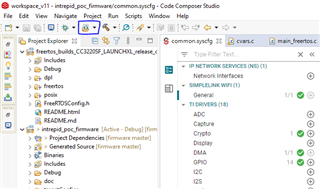
    I used Sysconfig in CCS to flash the firmware. I made sure to pick the correct project from the dropdown.

    Would it be the linker if it still debugs properly?

    I think the workflow for using Sysconfig in CCS is correct but hopefully from the screenshot above you can tell me if that's true.

    I am using the CC3220SF12ARGKR version of the MCU which is the 64 VQFN package. I pulled pin 57 to 3V3 (the same supply as the microcontroller) with a 6k8 resistor. I have double checked the datasheet, UART RX is configurable on other pins including 8, 17, 45, 57, and 59. It could very likely be one of these other pins that i need to pull high, I've taken another look in the user guide but I still don't see any mention of this RX pullup.

    Looking through the datasheet though I did see that the SOP lines have a 270Ohm series resistor to 3V3, I have them tied directly to 3V3. Do you think that could be the issue?

    Thanks again,

    Luke

  • Hi Luke,

    From image above I am not able confirm if your workflow is correct, but SLI Image programming is under that icon. I think you should check your workflow with SDK example(s).

    Yes. It is possible that you will be able debug via JTAG code which you will not be able executed from SPI flash. This is because JTAG can load directly into RAM or XIP (on-chip execution) flash. But for loading code from SPI flash it need to be build with proper enter point because code is loaded by ROM bootlaoder.

    Yes, UART pin 57 is right one. Can you test with different SOP mode (e.g. 0-0-0)?

    Current limiting resistor 270R at SOP lines is good to have, but I think it is not mandatory. Please see design checklist.

    Jan

  • So the problem was that I am dumb. If you have this same problem make sure you're not making the same mistake I did.

    The CC3220SF retains access point configuration between debug sessions but it wipes all of that when the memory is flashed. My device has no way to indicate this and so I didn't notice. you do not need a pull up resistor on the RX line as was suggested in the other thread on this post.

    Luke