Other Parts Discussed in Thread: CC3220SF
Hi,
I am trying to send data from C2000 (F28379D - LAUNCHXL ) to CC3220SF-LAUNCHXL using SPI Communication. But I am not able to send the data. Below is the code in c2000 device -
// FILE:   Lab1_cpu02.c

#include "F28x_Project.h"     // Device Header File and Examples Include File
#include <stddef.h>
#include <stdbool.h>
#include <stdint.h>
#include <string.h>


//Define the BaudRate=500KHz for 200MHz
#define SPI_BRR         ((200E6 / 4) / 500E3) - 1


// Variables
Uint16 sdata[2];     // Send data buffer
Uint16 rdata[2];     // Receive data buffer
Uint16 rdata_point;  // Keep track of where we are
                     // in the data stream to check received data

//Function Prototyes
void initGPIOs(void);
void initSpiaGpio(void);
void initSpia(void);
void initSpiFifo(void);
void spi_xmit(Uint16 a);
interrupt void spiTxFifoIsr(void);
interrupt void spiRxFifoIsr(void);
void delay_loop(void);
void error();


void main(void)
{

   Uint16 i;
// Initialize System Control
    InitSysCtrl();

//Initialize GPIOs
    initGPIOs();   //MAster, Slave, LED
    initSpiaGpio(); //SPI A GPIOs

// Disable CPU interrupts and initialize PIE control registers
    DINT;
    InitPieCtrl();

// Disable CPU interrupts and clear all CPU interrupt flags
    IER = 0x0000;
    IFR = 0x0000;

// Initialize the PIE vector table
    InitPieVectTable();

//
// ISR Mapping
//
    EALLOW;  // This is needed to write to EALLOW protected registers
    PieVectTable.SPIA_RX_INT = &spiRxFifoIsr;
    PieVectTable.SPIA_TX_INT = &spiTxFifoIsr;
    EDIS;    // This is needed to disable write to EALLOW protected registers


// Initialize SPI FIFO
    initSpiFifo();

//
// Initialize the send data buffer
//
    for(i=0; i<2; i++)
    {
      sdata[i] = i;
    }
    rdata_point = 0;


// Set Master Ready and wait for the Slave Ready - Handshaking

    GpioDataRegs.GPASET.bit.GPIO16 = 1;
    while(GpioDataRegs.GPADAT.bit.GPIO24 == 0){}

// Enable global Interrupts and higher priority real-time debug events
    PieCtrlRegs.PIECTRL.bit.ENPIE = 1;     // Enable the PIE block
    PieCtrlRegs.PIEIER6.bit.INTx1 = 1;     // Enable PIE Group 6, INT 1
    PieCtrlRegs.PIEIER6.bit.INTx2 = 1;     // Enable PIE Group 6, INT 2
    IER=0x20;                              // Enable CPU INT6
    EINT;          // Enable Global interrupt INTM
    ERTM;          // Enable Global realtime interrupt DBGM

    while(GpioDataRegs.GPADAT.bit.GPIO24 == 1){}


// Idle loop
    for(;;);
}


void initGPIOs(void)
{
        // Initialize  GPIOs
        EALLOW;
        //RED LED
        GpioCtrlRegs.GPBDIR.bit.GPIO34 = 1;
        GpioCtrlRegs.GPBGMUX1.bit.GPIO34 = 0;
        GpioCtrlRegs.GPBMUX1.bit.GPIO34 = 0;
        GpioDataRegs.GPBCLEAR.bit.GPIO34 = 1;

        //Master_Ready
        GpioCtrlRegs.GPADIR.bit.GPIO24 = 0;
        GpioCtrlRegs.GPAGMUX2.bit.GPIO24 = 0;
        GpioCtrlRegs.GPAMUX2.bit.GPIO24 = 0;
        GpioDataRegs.GPACLEAR.bit.GPIO24 = 1;


        //Slave_Ready
        GpioCtrlRegs.GPADIR.bit.GPIO16 = 1;
        GpioCtrlRegs.GPAGMUX2.bit.GPIO16 = 0;
        GpioCtrlRegs.GPAMUX2.bit.GPIO16 = 0;
        GpioDataRegs.GPACLEAR.bit.GPIO16 = 1;

        EDIS;
}
void initSpiaGpio(void)
{
    //SPI Initialization
    EALLOW;
    GpioCtrlRegs.GPBPUD.bit.GPIO58 = 0; // Enable pull-up on GPIO58 (SPISIMOA)
    GpioCtrlRegs.GPBPUD.bit.GPIO59 = 0; // Enable pull-up on GPIO59 (SPISOMIA)
    GpioCtrlRegs.GPBPUD.bit.GPIO60 = 0; // Enable pull-up on GPIO60 (SPICLKA)
    GpioCtrlRegs.GPBPUD.bit.GPIO61 = 0; // Enable pull-up on GPIO61 (SPISTEA)

    GpioCtrlRegs.GPBQSEL2.bit.GPIO58 = 3; // Asynch input GPIO58 (SPISIMOA)
    GpioCtrlRegs.GPBQSEL2.bit.GPIO59 = 3; // Asynch input GPIO59 (SPISOMIA)
    GpioCtrlRegs.GPBQSEL2.bit.GPIO60 = 3; // Asynch input GPIO60 (SPICLKA)
    GpioCtrlRegs.GPBQSEL2.bit.GPIO61 = 3; // Asynch input GPIO61 (SPISTEA)

    GpioCtrlRegs.GPBGMUX2.bit.GPIO58 = 3; // Configure GPIO58 as SPISIMOA
    GpioCtrlRegs.GPBGMUX2.bit.GPIO59 = 3; // Configure GPIO59 as SPISOMIA
    GpioCtrlRegs.GPBGMUX2.bit.GPIO60 = 3; // Configure GPIO60 as SPICLKA
    GpioCtrlRegs.GPBGMUX2.bit.GPIO61 = 3; // Configure GPIO61 as SPISTEA

    GpioCtrlRegs.GPBMUX2.bit.GPIO58 = 3; // Configure GPIO58 as SPISIMOA
    GpioCtrlRegs.GPBMUX2.bit.GPIO59 = 3; // Configure GPIO59 as SPISOMIA
    GpioCtrlRegs.GPBMUX2.bit.GPIO60 = 3; // Configure GPIO60 as SPICLKA
    GpioCtrlRegs.GPBMUX2.bit.GPIO61 = 3; // Configure GPIO61 as SPISTEA

    EDIS;
}


void initSpiFifo(void)
{
    /*
    //
    // Initialize SPI FIFO registers
    //
    SpiaRegs.SPIFFTX.all = 0xE040;
    SpiaRegs.SPIFFRX.all = 0x2044;
    SpiaRegs.SPIFFCT.all = 0x0;*/
    //
    // Initialize SPI FIFO registers
    //
    SpiaRegs.SPIFFTX.all = 0xC022;    // Enable FIFOs, set TX FIFO level to 2
    SpiaRegs.SPIFFRX.all = 0x0022;    // Set RX FIFO level to 2
    SpiaRegs.SPIFFCT.all = 0x00;

    SpiaRegs.SPIFFTX.bit.TXFIFO=1;
    SpiaRegs.SPIFFRX.bit.RXFIFORESET=1;

    initSpia();
}


void initSpia(void)
{
    // Initialize SPI-A

    // Set reset low before configuration changes
    // Enable master (0 == slave, 1 == master)
    SpiaRegs.SPICCR.bit.SPISWRESET = 0;
    SpiaRegs.SPICTL.bit.MASTER_SLAVE = 0;

    // Set the baud rate
    SpiaRegs.SPIBRR.bit.SPI_BIT_RATE = SPI_BRR;


    // Clock polarity (0 == rising, 1 == falling)
    // Clock phase (0 == normal, 1 == delayed)
    SpiaRegs.SPICCR.bit.CLKPOLARITY = 0;
    SpiaRegs.SPICTL.bit.CLK_PHASE = 0;

    // 16-bit character
    // Disable loop-back
    SpiaRegs.SPICCR.bit.SPICHAR = (16-1);
    SpiaRegs.SPICCR.bit.SPILBK = 0;

    //Clear SPI Flag
    SpiaRegs.SPISTS.bit.INT_FLAG = 0;
    SpiaRegs.SPISTS.bit.OVERRUN_FLAG = 0;

    // Enable transmission (Talk)
    // SPI interrupts are disabled
    SpiaRegs.SPICTL.bit.TALK = 0;
    SpiaRegs.SPICTL.bit.SPIINTENA = 0;

    // Set FREE bit
    // Halting on a breakpoint will not halt the SPI
    SpiaRegs.SPIPRI.bit.FREE = 1;

    // Release the SPI from reset
    SpiaRegs.SPICCR.bit.SPISWRESET = 1;

}

//
// spiTxFifoIsr - ISR for SPI transmit FIFO
//
interrupt void spiTxFifoIsr(void)
{
    Uint16 i;
    for(i=0;i<2;i++)
    {
       SpiaRegs.SPITXBUF=sdata[i];      // Send data
    }

    for(i=0;i<2;i++)                    // Increment data for next cycle
    {
       sdata[i] = sdata[i] + 1;
    }

    SpiaRegs.SPIFFTX.bit.TXFFINTCLR=1;  // Clear Interrupt flag
    PieCtrlRegs.PIEACK.all|=0x20;       // Issue PIE ACK
}

//
// spiRxFifoIsr - ISR for SPI receive FIFO
//
interrupt void spiRxFifoIsr(void)
{
    Uint16 i;

    for(i=0; i<2; i++)
    {
        rdata[i]=SpiaRegs.SPIRXBUF;     // Read data
    }

    for(i=0; i<2; i++)                  // Check received data
    {
        if(rdata[i] != rdata_point+i)
        {
            error();
        }
    }

    rdata_point++;
    SpiaRegs.SPIFFRX.bit.RXFFOVFCLR=1;  // Clear Overflow flag
    SpiaRegs.SPIFFRX.bit.RXFFINTCLR=1;  // Clear Interrupt flag
    PieCtrlRegs.PIEACK.all|=0x20;       // Issue PIE ack
}


void spi_xmit(Uint16 a)
{
    SpiaRegs.SPITXBUF=a;
}


//
// delay_loop - Function to provide delay
//
void delay_loop()
{
    long i;
    for (i = 0; i < 1000000; i++) {}
}

//
// error - Function to halt debugger on error
//
void error(void)
{
    asm("     ESTOP0");  //Test failed!! Stop!
    for (;;);
}

// end of file
Similarly, I am having the master code in CC3220SF as shown below -
/*
* Copyright (c) 2018-2019, Texas Instruments Incorporated
* All rights reserved.
*
* Redistribution and use in source and binary forms, with or without
* modification, are permitted provided that the following conditions
* are met:
*
* * Redistributions of source code must retain the above copyright
* notice, this list of conditions and the following disclaimer.
*
* * Redistributions in binary form must reproduce the above copyright
* notice, this list of conditions and the following disclaimer in the
* documentation and/or other materials provided with the distribution.
*
* * Neither the name of Texas Instruments Incorporated nor the names of
* its contributors may be used to endorse or promote products derived
* from this software without specific prior written permission.
*
* THIS SOFTWARE IS PROVIDED BY THE COPYRIGHT HOLDERS AND CONTRIBUTORS "AS IS"
* AND ANY EXPRESS OR IMPLIED WARRANTIES, INCLUDING, BUT NOT LIMITED TO,
* THE IMPLIED WARRANTIES OF MERCHANTABILITY AND FITNESS FOR A PARTICULAR
* PURPOSE ARE DISCLAIMED. IN NO EVENT SHALL THE COPYRIGHT OWNER OR
* CONTRIBUTORS BE LIABLE FOR ANY DIRECT, INDIRECT, INCIDENTAL, SPECIAL,
* EXEMPLARY, OR CONSEQUENTIAL DAMAGES (INCLUDING, BUT NOT LIMITED TO,
* PROCUREMENT OF SUBSTITUTE GOODS OR SERVICES; LOSS OF USE, DATA, OR PROFITS;
* OR BUSINESS INTERRUPTION) HOWEVER CAUSED AND ON ANY THEORY OF LIABILITY,
* WHETHER IN CONTRACT, STRICT LIABILITY, OR TORT (INCLUDING NEGLIGENCE OR
* OTHERWISE) ARISING IN ANY WAY OUT OF THE USE OF THIS SOFTWARE,
* EVEN IF ADVISED OF THE POSSIBILITY OF SUCH DAMAGE.
*/
/*
* ======== spimaster.c ========
*/
#include <stddef.h>
#include <stdint.h>
#include <string.h>
/* POSIX Header files */
#include <pthread.h>
#include <semaphore.h>
#include <unistd.h>
/* Driver Header files */
#include <ti/drivers/GPIO.h>
#include <ti/drivers/SPI.h>
#include <ti/display/Display.h>
/* Driver configuration */
#include "ti_drivers_config.h"
#define THREADSTACKSIZE (1024)
#define SPI_MSG_LENGTH (30)
#define MASTER_MSG ("Hello from master, msg#: ")
#define MAX_LOOP (10)
static Display_Handle display;
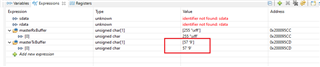
unsigned char masterRxBuffer[SPI_MSG_LENGTH];
unsigned char masterTxBuffer[SPI_MSG_LENGTH];
/* Semaphore to block master until slave is ready for transfer */
sem_t masterSem;
/*
* ======== slaveReadyFxn ========
* Callback function for the GPIO interrupt on CONFIG_SPI_SLAVE_READY.
*/
void slaveReadyFxn(uint_least8_t index)
{
sem_post(&masterSem);
}
/*
* ======== masterThread ========
* Master SPI sends a message to slave while simultaneously receiving a
* message from the slave.
*/
void *masterThread(void *arg0)
{
SPI_Handle masterSpi;
SPI_Params spiParams;
SPI_Transaction transaction;
uint32_t i;
bool transferOK;
int32_t status;
/*
* CONFIG_SPI_MASTER_READY & CONFIG_SPI_SLAVE_READY are GPIO pins connected
* between the master & slave. These pins are used to synchronize
* the master & slave applications via a small 'handshake'. The pins
* are later used to synchronize transfers & ensure the master will not
* start a transfer until the slave is ready. These pins behave
* differently between spimaster & spislave examples:
*
* spimaster example:
* * CONFIG_SPI_MASTER_READY is configured as an output pin. During the
* 'handshake' this pin is changed from low to high output. This
* notifies the slave the master is ready to run the application.
* Afterwards, the pin is used by the master to notify the slave it
* has opened CONFIG_SPI_MASTER. When CONFIG_SPI_MASTER is opened, this
* pin will be pulled low.
*
* * CONFIG_SPI_SLAVE_READY is configured as an input pin. During the
* 'handshake' this pin is read & a high value will indicate the slave
* ready to run the application. Afterwards, a falling edge interrupt
* will be configured on this pin. When the slave is ready to perform
* a transfer, it will pull this pin low.
*
* Below we set CONFIG_SPI_MASTER_READY & CONFIG_SPI_SLAVE_READY initial
* conditions for the 'handshake'.
*/
GPIO_setConfig(CONFIG_SPI_MASTER_READY, GPIO_CFG_OUTPUT | GPIO_CFG_OUT_LOW);
GPIO_setConfig(CONFIG_SPI_SLAVE_READY, GPIO_CFG_INPUT);
/*
* Handshake - Set CONFIG_SPI_MASTER_READY high to indicate master is ready
* to run. Wait CONFIG_SPI_SLAVE_READY to be high.
*/
GPIO_write(CONFIG_SPI_MASTER_READY, 1);
while (GPIO_read(CONFIG_SPI_SLAVE_READY) == 0) {}
/* Handshake complete; now configure interrupt on CONFIG_SPI_SLAVE_READY */
GPIO_setConfig(CONFIG_SPI_SLAVE_READY, GPIO_CFG_IN_PU | GPIO_CFG_IN_INT_FALLING);
GPIO_setCallback(CONFIG_SPI_SLAVE_READY, slaveReadyFxn);
GPIO_enableInt(CONFIG_SPI_SLAVE_READY);
/*
* Create synchronization semaphore; the master will wait on this semaphore
* until the slave is ready.
*/
status = sem_init(&masterSem, 0, 0);
if (status != 0) {
Display_printf(display, 0, 0, "Error creating masterSem\n");
while(1);
}
/* Open SPI as master (default) */
SPI_Params_init(&spiParams);
spiParams.frameFormat = SPI_POL0_PHA1;
spiParams.bitRate = 10000000;
masterSpi = SPI_open(CONFIG_SPI_MASTER, &spiParams);
if (masterSpi == NULL) {
Display_printf(display, 0, 0, "Error initializing master SPI\n");
while (1);
}
else {
Display_printf(display, 0, 0, "Master SPI initialized\n");
}
/*
* Master has opened CONFIG_SPI_MASTER; set CONFIG_SPI_MASTER_READY high to
* inform the slave.
*/
GPIO_write(CONFIG_SPI_MASTER_READY, 0);
/* Copy message to transmit buffer */
strncpy((char *) masterTxBuffer, MASTER_MSG, SPI_MSG_LENGTH);
for (i = 0; i < MAX_LOOP; i++) {
/*
* Wait until slave is ready for transfer; slave will pull
* CONFIG_SPI_SLAVE_READY low.
*/
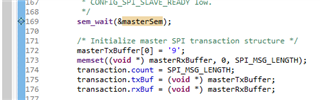
sem_wait(&masterSem);
/* Initialize master SPI transaction structure */
masterTxBuffer[sizeof(MASTER_MSG) - 1] = (i % 10) + '0';
memset((void *) masterRxBuffer, 0, SPI_MSG_LENGTH);
transaction.count = SPI_MSG_LENGTH;
transaction.txBuf = (void *) masterTxBuffer;
transaction.rxBuf = (void *) masterRxBuffer;
/* Toggle user LED, indicating a SPI transfer is in progress */
GPIO_toggle(CONFIG_GPIO_LED_1);
/* Perform SPI transfer */
transferOK = SPI_transfer(masterSpi, &transaction);
if (transferOK) {
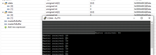
Display_printf(display, 0, 0, "Master received: %s", masterRxBuffer);
}
else {
Display_printf(display, 0, 0, "Unsuccessful master SPI transfer");
}
/* Sleep for a bit before starting the next SPI transfer */
sleep(3);
}
SPI_close(masterSpi);
/* Example complete - set pins to a known state */
GPIO_disableInt(CONFIG_SPI_SLAVE_READY);
GPIO_setConfig(CONFIG_SPI_SLAVE_READY, GPIO_CFG_OUTPUT | GPIO_CFG_OUT_LOW);
GPIO_write(CONFIG_SPI_MASTER_READY, 0);
Display_printf(display, 0, 0, "\nDone");
return (NULL);
}
/*
* ======== mainThread ========
*/
void *mainThread(void *arg0)
{
pthread_t thread0;
pthread_attr_t attrs;
struct sched_param priParam;
int retc;
int detachState;
/* Call driver init functions. */
Display_init();
GPIO_init();
SPI_init();
/* Configure the LED pins */
GPIO_setConfig(CONFIG_GPIO_LED_0, GPIO_CFG_OUT_STD | GPIO_CFG_OUT_LOW);
GPIO_setConfig(CONFIG_GPIO_LED_1, GPIO_CFG_OUT_STD | GPIO_CFG_OUT_LOW);
/* Open the display for output */
display = Display_open(Display_Type_UART, NULL);
if (display == NULL) {
/* Failed to open display driver */
while (1);
}
/* Turn on user LED */
GPIO_write(CONFIG_GPIO_LED_0, CONFIG_GPIO_LED_ON);
Display_printf(display, 0, 0, "Starting the SPI master example");
Display_printf(display, 0, 0, "This example requires external wires to be "
"connected to the header pins. Please see the Board.html for details.\n");
/* Create application threads */
pthread_attr_init(&attrs);
detachState = PTHREAD_CREATE_DETACHED;
/* Set priority and stack size attributes */
retc = pthread_attr_setdetachstate(&attrs, detachState);
if (retc != 0) {
/* pthread_attr_setdetachstate() failed */
while (1);
}
retc |= pthread_attr_setstacksize(&attrs, THREADSTACKSIZE);
if (retc != 0) {
/* pthread_attr_setstacksize() failed */
while (1);
}
/* Create master thread */
priParam.sched_priority = 1;
pthread_attr_setschedparam(&attrs, &priParam);
retc = pthread_create(&thread0, &attrs, masterThread, NULL);
if (retc != 0) {
/* pthread_create() failed */
while (1);
}
return (NULL);
}
I have tried connecting two c2000 devices using SPI and that is working using the above code for c2000 but I am not able to send the data in between c2000 and cc3220SF. Can anyone help for this, Its a urgent requirement?
Thank You,
Regards,
Kuldeep